Pages

Tuesday, October 13, 2009

Central Processing Unit

The central processing unit (CPU) is the portion of a computer system that carries out the instructions of a computer program, and is the primary element carrying out the computer's functions. The central processing unit carries out each instruction of the program in sequence, to perform the basic arithmetical, logical, and input/output operations of the system. This term has been in use in the computer industry at least since the early 1960s. The form, design and implementation of CPUs have changed dramatically since the earliest examples, but their fundamental operation remains much the same.
Early CPUs were custom-designed as a part of a larger, sometimes one-of-a-kind, computer. However, this costly method of designing custom CPUs for a particular application has largely given way to the development of mass-produced processors that are made for one or many purposes. This standardization trend generally began in the era of discrete transistor mainframes and minicomputers and has rapidly accelerated with the popularization of the integrated circuit (IC). The IC has allowed increasingly complex CPUs to be designed and manufactured to tolerances on the order of nanometers. Both the miniaturization and standardization of CPUs have increased the presence of these digital devices in modern life far beyond the limited application of dedicated computing machines. Modern microprocessors appear in everything from automobiles to cell phones and children's toys.

History
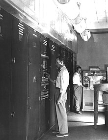
EDVAC, one of the first electronic stored program computers.

Computers such as the ENIAC had to be physically rewired in order to perform different tasks, which caused these machines to be called "fixed-program computers." Since the term "CPU" is generally defined as a software (computer program) execution device, the earliest devices that could rightly be called CPUs came with the advent of the stored-program computer.
The idea of a stored-program computer was already present in the design of J. Presper Eckert and John William Mauchly's ENIAC, but was initially omitted so the machine could be finished sooner. On June 30, 1945, before ENIAC was even completed, mathematician John von Neumann distributed the paper entitled First Draft of a Report on the EDVAC. It outlined the design of a stored-program computer that would eventually be completed in August 1949. EDVAC was designed to perform a certain number of instructions (or operations) of various types. These instructions could be combined to create useful programs for the EDVAC to run. Significantly, the programs written for EDVAC were stored in high-speed computer memory rather than specified by the physical wiring of the computer. This overcame a severe limitation of ENIAC, which was the considerable time and effort required to reconfigure the computer to perform a new task. With von Neumann's design, the program, or software, that EDVAC ran could be changed simply by changing the contents of the computer's memory.
While von Neumann is most often credited with the design of the stored-program computer because of his design of EDVAC, others before him, such as Konrad Zuse, had suggested and implemented similar ideas. The so-called Harvard architecture of the Harvard Mark I, which was completed before EDVAC, also utilized a stored-program design using punched paper tape rather than electronic memory. The key difference between the von Neumann and Harvard architectures is that the latter separates the storage and treatment of CPU instructions and data, while the former uses the same memory space for both. Most modern CPUs are primarily von Neumann in design, but elements of the Harvard architecture are commonly seen as well.
As a digital device, a CPU is limited to a set of discrete states, and requires some kind of switching elements to differentiate between and change states. Prior to commercial development of the transistor, electrical relays and vacuum tubes (thermionic valves) were commonly used as switching elements. Although these had distinct speed advantages over earlier, purely mechanical designs, they were unreliable for various reasons. For example, building direct current sequential logic circuits out of relays requires additional hardware to cope with the problem of contact bounce. While vacuum tubes do not suffer from contact bounce, they must heat up before becoming fully operational, and they eventually cease to function due to slow contamination of their cathodes that occurs in the course of normal operation. If a tube's vacuum seal leaks, as sometimes happens, cathode contamination is accelerated. Usually, when a tube failed, the CPU would have to be diagnosed to locate the failed component so it could be replaced. Therefore, early electronic (vacuum tube based) computers were generally faster but less reliable than electromechanical (relay based) computers.
Tube computers like EDVAC tended to average eight hours between failures, whereas relay computers like the (slower, but earlier) Harvard Mark I failed very rarely. In the end, tube based CPUs became dominant because the significant speed advantages afforded generally outweighed the reliability problems. Most of these early synchronous CPUs ran at low clock rates compared to modern microelectronic designs (see below for a discussion of clock rate). Clock signal frequencies ranging from 100 kHz to 4 MHz were very common at this time, limited largely by the speed of the switching devices they were built with.

Operation
The fundamental operation of most CPUs, regardless of the physical form they take, is to execute a sequence of stored instructions called a program. The program is represented by a series of numbers that are kept in some kind of computer memory. There are four steps that nearly all CPUs use in their operation: fetch, decode, execute, and writeback.
The first step, fetch, involves retrieving an instruction (which is represented by a number or sequence of numbers) from program memory. The location in program memory is determined by a program counter (PC), which stores a number that identifies the current position in the program. In other words, the program counter keeps track of the CPU's place in the program. After an instruction is fetched, the PC is incremented by the length of the instruction word in terms of memory units. Often the instruction to be fetched must be retrieved from relatively slow memory, causing the CPU to stall while waiting for the instruction to be returned. This issue is largely addressed in modern processors by caches and pipeline architectures (see below).
The instruction that the CPU fetches from memory is used to determine what the CPU is to do. In the decode step, the instruction is broken up into parts that have significance to other portions of the CPU. The way in which the numerical instruction value is interpreted is defined by the CPU's instruction set architecture (ISA). Often, one group of numbers in the instruction, called the opcode, indicates which operation to perform. The remaining parts of the number usually provide information required for that instruction, such as operands for an addition operation. Such operands may be given as a constant value (called an immediate value), or as a place to locate a value: a register or a memory address, as determined by some addressing mode. In older designs the portions of the CPU responsible for instruction decoding were unchangeable hardware devices. However, in more abstract and complicated CPUs and ISAs, a microprogram is often used to assist in translating instructions into various configuration signals for the CPU. This microprogram is sometimes rewritable so that it can be modified to change the way the CPU decodes instructions even after it has been manufactured.
After the fetch and decode steps, the execute step is performed. During this step, various portions of the CPU are connected so they can perform the desired operation. If, for instance, an addition operation was requested, an arithmetic logic unit (ALU) will be connected to a set of inputs and a set of outputs. The inputs provide the numbers to be added, and the outputs will contain the final sum. The ALU contains the circuitry to perform simple arithmetic and logical operations on the inputs (like addition and bitwise operations). If the addition operation produces a result too large for the CPU to handle, an arithmetic overflow flag in a flags register may also be set.
The final step, writeback, simply "writes back" the results of the execute step to some form of memory. Very often the results are written to some internal CPU register for quick access by subsequent instructions. In other cases results may be written to slower, but cheaper and larger, main memory. Some types of instructions manipulate the program counter rather than directly produce result data. These are generally called "jumps" and facilitate behavior like loops, conditional program execution (through the use of a conditional jump), and functions in programs. Many instructions will also change the state of digits in a "flags" register. These flags can be used to influence how a program behaves, since they often indicate the outcome of various operations. For example, one type of "compare" instruction considers two values and sets a number in the flags register according to which one is greater. This flag could then be used by a later jump instruction to determine program flow.
After the execution of the instruction and writeback of the resulting data, the entire process repeats, with the next instruction cycle normally fetching the next-in-sequence instruction because of the incremented value in the program counter. If the completed instruction was a jump, the program counter will be modified to contain the address of the instruction that was jumped to, and program execution continues normally. In more complex CPUs than the one described here, multiple instructions can be fetched, decoded, and executed simultaneously. This section describes what is generally referred to as the "Classic RISC pipeline", which in fact is quite common among the simple CPUs used in many electronic devices (often called microcontroller). It largely ignores the important role of CPU cache, and therefore the access stage of the pipeline.

Wednesday, October 7, 2009

Video Graphics Array

Video Graphics Array (VGA) refers specifically to the display hardware first introduced with the IBM PS/2 line of computers in 1987, but through its widespread adoption has also come to mean either an analog computer display standard, the 15-pin D-subminiature VGA connector or the 640×480 resolution itself. While this resolution was superseded in the personal computer market in the 1990s, it is becoming a popular resolution on mobile devices.
VGA was the last graphical standard introduced by IBM that the majority of PC clone manufacturers conformed to, making it today (as of 2010) the lowest common denominator that all PC graphics hardware can be expected to implement without device-specific driver software. For example, the Microsoft Windows splash screen appears while the machine is still operating in VGA mode, which is the reason that this screen always appears in reduced resolution and color depth.
VGA was officially superseded by IBM's Extended Graphics Array (XGA) standard, but in reality it was superseded by numerous slightly different extensions to VGA made by clone manufacturers that came to be known collectively as Super VGA.

Hardware
VGA compared to other standard resolutions.

VGA is referred to as an "array" instead of an "adapter" because it was implemented from the start as a single chip (an ASIC), replacing the Motorola 6845 and dozens of discrete logic chips that covered the full-length ISA boards of the MDA, CGA, and EGA. Its single-chip implementation also allowed the VGA to be placed directly on a PC's motherboard with a minimum of difficulty (it only required video memory, timing crystals and an external RAMDAC), and the first IBM PS/2 models were equipped with VGA on the motherboard. (Contrast this with all of the "family one" IBM PC desktop models—the PC [machine-type 5150], PC/XT [5160], and PC AT [5170]—which required a display adapter installed in a slot in order to connect a monitor.)
The VGA specifications are as follows:

  • 256 KB Video RAM (The very first cards could be ordered with 64 KB or 128 KB of RAM at the cost of losing some video modes).
  • 16-color and 256-color modes
  • 262,144-value color palette (six bits each for red, green, and blue)
  • Selectable 25.175 MHz or 28.322 MHz master clock
  • Maximum of 800 horizontal pixels
  • Maximum of 600 lines
  • Refresh rates at up to 70 Hz
  • Vertical blank interrupt (Not all clone cards support this.)
  • Planar mode: up to 16 colors (4 bit planes)
  • Packed-pixel mode: 256 colors (Mode 13h)
  • Hardware smooth scrolling support
  • Some "Raster Ops" support
  • Barrel shifter
  • Split screen support
  • 0.7 V peak-to-peak
  • 75 ohm double-terminated impedance (18.7 mA – 13 mW)

The VGA supports both All Points Addressable graphics modes, and alphanumeric text modes. Standard graphics modes are:

  • 640×480 in 16 colors
  • 640×350 in 16 colors
  • 320×200 in 16 colors
  • 320×200 in 256 colors (Mode 13h)

As well as the standard modes, VGA can be configured to emulate many of the modes of its predecessors (EGA, CGA, and MDA). Compatibility is almost full at BIOS level, but even at register level, a very high value of compatibility is reached. VGA is not compatible with the special IBM PCjr or HGC video modes.

Tuesday, October 6, 2009

CD-ROM

CD-ROM (pronounced /ˌsiːˌdiːˈrɒm/, an acronym of "compact disc read-only memory") is a pre-pressed compact disc that contains data accessible to, but not writable by, a computer for data storage and music playback. The 1985 “Yellow Book” standard developed by Sony and Philips adapted the format to hold any form of binary data.

CD-ROMs are popularly used to distribute computer software, including games and multimedia applications, though any data can be stored (up to the capacity limit of a disc). Some CDs hold both computer data and audio with the latter capable of being played on a CD player, while data (such as software or digital video) is only usable on a computer (such as ISO 9660 format PC CD-ROMs). These are called enhanced CDs.
Although many people use lowercase letters in this acronym, proper presentation is in all capital letters with a hyphen between CD and ROM. At the time of the technology's introduction it had more capacity than computer hard drives common at the time. The reverse is now true, with hard drives far exceeding CDs, DVDs and Blu-ray, though some experimental descendants of it such as HVDs may have more space and faster data rates than today's biggest hard drive.

Media
CD-ROM discs are identical in appearance to audio CDs, and data are stored and retrieved in a very similar manner (only differing from audio CDs in the standards used to store the data). Discs are made from a 1.2 mm thick disc of polycarbonate plastic, with a thin layer of aluminium to make a reflective surface. The most common size of CD-ROM disc is 120 mm in diameter, though the smaller Mini CD standard with an 80 mm diameter, as well as numerous non-standard sizes and shapes (e.g., business card-sized media) are also available. Data is stored on the disc as a series of microscopic indentations. A laser is shone onto the reflective surface of the disc to read the pattern of pits and lands ("pits", with the gaps between them referred to as "lands"). Because the depth of the pits is approximately one-quarter to one-sixth of the wavelength of the laser light used to read the disc, the reflected beam's phase is shifted in relation to the incoming beam, causing destructive interference and reducing the reflected beam's intensity. This pattern of changing intensity of the reflected beam is converted into binary data.

Standard
Several formats are used for data stored on compact discs, known as the Rainbow Books. These include the original Red Book standards for CD audio, White Book and Yellow Book CD-ROM. The ISO/IEC 10149 / ECMA-130 standard, which gives a thorough description of the physics and physical layer of the CD-ROM, inclusive of cross-interleaved Reed-Solomon coding (CIRC) and eight-to-fourteen modulation (EFM), can be downloaded from ISO or ECMA.
ISO 9660 defines the standard file system of a CD-ROM, although it is due to be replaced by ISO 13490 (which also supports CD-R and multi-session). UDF extends ISO 13346 (which was designed for non-sequential write-once and re-writeable discs such as CD-R and CD-RW) to support read-only and re-writeable media and was first adopted for DVD. The bootable CD specification, to make a CD emulate a hard disk or floppy, is called El Torito.
CD-ROM drives are rated with a speed factor relative to music CDs (1× or 1-speed which gives a data transfer rate of 150 KiB/s). 12× drives were common beginning in early 1997. Above 12× speed, there are problems with vibration and heat. Constant angular velocity (CAV) drives give speeds up to 30× at the outer edge of the disc with the same rotational speed as a standard constant linear velocity (CLV) 12×, or 32× with a slight increase. However due to the nature of CAV (linear speed at the inner edge is still only 12×, increasing smoothly in-between) the actual throughput increase is less than 30/12 – in fact, roughly 20× average for a completely full disc, and even less for a partially filled one.
Problems with vibration, owing to e.g. limits on achievable symmetry and strength in mass produced media, mean that CDROM drive speeds have not massively increased since the late 90s. Over 10 years later, commonly available drives vary between 24× (slimline and portable units, 10× spin speed) and 52× (typically CD- and read-only units, 21× spin speed), all using CAV to achieve their claimed "max" speeds, with 32× through 48× most common. Even so, these speeds can cause poor reading (drive error correction having become very sophisticated in response) and even shattering of poorly made or physically damaged media, with small cracks rapidly growing into catastrophic breakages when centripetally stressed at 10,000 – 13,000rpm (i.e. 40–52× CAV). High rotational speeds also produce undesirable noise from disc vibration, rushing air and the spindle motor itself. Thankfully, most 21st century drives allow forced low speed modes (by use of small utility programs) for the sake of safety, accurate reading or silence, and will automatically fall back if a large number of sequential read errors and retries are encountered.
Other methods of improving read speed were trialled such as using multiple pickup heads, increasing throughput up to 72× with a 10× spin speed, but along with other technologies like 90~99 minute recordable media and "double density" recorders, their utility was nullified by the introduction of consumer DVDROM drives capable of consistent 36× CDROM speeds (4× DVD) or higher. Additionally, with a 700mb CDROM fully readable in under 2½ minutes at 52× CAV, increases in actual data transfer rate are decreasingly influential on overall effective drive speed when taken into consideration with other factors such as loading/unloading, media recognition, spin up/down and random seek times, making for much decreased returns on development investment. A similar stratification effect has since been seen in DVD development where maximum speed has stabilised at 16× CAV (with exceptional cases between 18× and 22×) and capacity at 4.3 and 8.5GiB (single and dual layer), with higher speed and capacity needs instead being catered to by Blu-Ray drives.

CD-ROM format
A CD-ROM sector contains 2,352 bytes, divided into 98 24-byte frames. Unlike a music CD, a CD-ROM cannot rely on error concealment by interpolation, and therefore requires a higher reliability of the retrieved data. In order to achieve improved error correction and detection, a CD-ROM has a third layer of Reed–Solomon error correction. A Mode-1 CD-ROM, which has the full three layers of error correction data, contains a net 2,048 bytes of the available 2,352 per sector. In a Mode-2 CD-ROM, which is mostly used for video files, there are 2,336 user-available bytes per sector. The net byte rate of a Mode-1 CD-ROM, based on comparison to CDDA audio standards, is 44100 Hz × 16 bits/sample × 2 channels × 2,048 / 2,352 /8 = 153.6 kB/s = 150 KiB/s. The playing time is 74 minutes, or 4,440 seconds, so that the net capacity of a Mode-1 CD-ROM is 682 MB or, equivalently, 650 MiB.
A 1× speed CD drive reads 75 consecutive sectors per second.

Wednesday, September 23, 2009

Hard Disk Drive

A hard disk drive (HDD) is a non-volatile, random access device for digital data. It features rotating rigid platters on a motor-driven spindle within a protective enclosure. Data is magnetically read and written on the platter by read/write heads that float on a film of air above the platters.

Introduced by IBM in 1956, hard disk drives have fallen in cost and physical size over the years while dramatically increasing capacity. Hard disk drives have been the dominant device for secondary storage of data in general purpose computers since the early 1960s. They have maintained this position because advances in their areal recording density have kept pace with the requirements for secondary storage. Today's HDDs operate on high-speed serial interfaces; i.e., serial ATA (SATA) or serial attached SCSI (SAS).

History
Hard disk drives were introduced in 1956 as data storage for an IBM accounting computer) and were developed for use with general purpose mainframe and mini computers.
Driven by areal density doubling every two to four years since their invention, HDDs have changed in many ways, a few highlights include:
Capacity per HDD increasing from 3.75 megabytes to greater than 1 terabyte, a greater than 270 thousand to 1 improvement.
Size of HDD decreasing from 87.9 cubic feet (a double wide refrigerator) to 0.002 cubic feet (2½-inch form factor, a pack of cards), a greater than 44 thousand to 1 improvement.
Price decreasing from about $15,000 per megabyte to less than $0.0001 per megabyte ($100/1 terabyte), a greater than 150 million to 1 improvement
Average access time decreasing from greater than 0.1 second to a few thousandths of a second, a greater than 40 to 1 improvement.
Market application expanding from general purpose computers to most computing applications including consumer applications.

Technology

Magnetic recording
HDDs record data by magnetizing ferromagnetic material directionally. Sequential changes in the direction of magnetization represent patterns of binary data bits. The data are read from the disk by detecting the transitions in magnetization and decoding the originally written data. Different encoding schemes, such as Modified Frequency Modulation, group code recording, run-length limited encoding, and others are used.
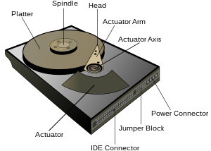
A typical HDD design consists of a spindle that holds flat circular disks called platters, onto which the data are recorded. The platters are made from a non-magnetic material, usually aluminum alloy or glass, and are coated with a shallow layer of magnetic material, typically 10–20 nm in depth—for reference, standard copy paper is 0.07–0.18 millimetre (70,000–180,000 nm)—with an outer layer of carbon for protection.
The platters are spun at speeds varying from 3,000 RPM in energy-efficient portable devices, to 15,000 RPM for high performance servers. Information is written to, and read from a platter as it rotates past devices called read-and-write heads that operate very close (tens of nanometers in new drives) over the magnetic surface. The read-and-write head is used to detect and modify the magnetization of the material immediately under it. In modern drives there is one head for each magnetic platter surface on the spindle, mounted on a common arm. An actuator arm (or access arm) moves the heads on an arc (roughly radially) across the platters as they spin, allowing each head to access almost the entire surface of the platter as it spins. The arm is moved using a voice coil actuator or in some older designs a stepper motor.
The magnetic surface of each platter is conceptually divided into many small sub-micrometer-sized magnetic regions referred to as magnetic domains. In older disk designs the regions were oriented horizontally and parallel to the disk surface, but beginning about 2005, the orientation was changed to perpendicular to allow for closer magnetic domain spacing. Due to the polycrystalline nature of the magnetic material each of these magnetic regions is composed of a few hundred magnetic grains. Magnetic grains are typically 10 nm in size and each form a single magnetic domain. Each magnetic region in total forms a magnetic dipole which generates a magnetic field.
For reliable storage of data, the recording material needs to resist self-demagnetization, which occurs when the magnetic domains repel each other. Magnetic domains written too densely together to a weakly magnetizable material will degrade over time due to physical rotation of one or more domains to cancel out these forces. The domains rotate sideways to a halfway position that weakens the readability of the domain and relieves the magnetic stresses. Older hard disks used iron(III) oxide as the magnetic material, but current disks use a cobalt-based alloy.
A write head magnetizes a region by generating a strong local magnetic field. Early HDDs used an electromagnet both to magnetize the region and to then read its magnetic field by using electromagnetic induction. Later versions of inductive heads included metal in Gap (MIG) heads and thin film heads. As data density increased, read heads using magnetoresistance (MR) came into use; the electrical resistance of the head changed according to the strength of the magnetism from the platter. Later development made use of spintronics; in these heads, the magnetoresistive effect was much greater than in earlier types, and was dubbed "giant" magnetoresistance (GMR). In today's heads, the read and write elements are separate, but in close proximity, on the head portion of an actuator arm. The read element is typically magneto-resistive while the write element is typically thin-film inductive.
The heads are kept from contacting the platter surface by the air that is extremely close to the platter; that air moves at or near the platter speed. The record and playback head are mounted on a block called a slider, and the surface next to the platter is shaped to keep it just barely out of contact. This forms a type of air bearing.
In modern drives, the small size of the magnetic regions creates the danger that their magnetic state might be lost because of thermal effects. To counter this, the platters are coated with two parallel magnetic layers, separated by a 3-atom layer of the non-magnetic element ruthenium, and the two layers are magnetized in opposite orientation, thus reinforcing each other. Another technology used to overcome thermal effects to allow greater recording densities is perpendicular recording, first shipped in 2005, and as of 2007 the technology was used in many HDDs.

Components
A typical hard drive has two electric motors, one to spin the disks and one to position the read/write head assembly. The disk motor has an external rotor attached to the platters; the stator windings are fixed in place. The actuator has a read-write head under the tip of its very end (near center); a thin printed-circuit cable connects the read-write head to the hub of the actuator. A flexible, somewhat U-shaped, ribbon cable, seen edge-on below and to the left of the actuator arm in the first image and more clearly in the second, continues the connection from the head to the controller board on the opposite side.
The head support arm is very light, but also stiff; in modern drives, acceleration at the head reaches 550 Gs.
The silver-colored structure at the upper left of the first image is the top plate of the permanent-magnet and moving coil motor that swings the heads to the desired position (it is shown removed in the second image). The plate supports a squat neodymium-iron-boron (NIB) high-flux magnet. Beneath this plate is the moving coil, often referred to as the voice coil by analogy to the coil in loudspeakers, which is attached to the actuator hub, and beneath that is a second NIB magnet, mounted on the bottom plate of the motor (some drives only have one magnet).
The voice coil itself is shaped rather like an arrowhead, and made of doubly coated copper magnet wire. The inner layer is insulation, and the outer is thermoplastic, which bonds the coil together after it is wound on a form, making it self-supporting. The portions of the coil along the two sides of the arrowhead (which point to the actuator bearing center) interact with the magnetic field, developing a tangential force that rotates the actuator. Current flowing radially outward along one side of the arrowhead and radially inward on the other produces the tangential force. If the magnetic field were uniform, each side would generate opposing forces that would cancel each other out. Therefore the surface of the magnet is half N pole, half S pole, with the radial dividing line in the middle, causing the two sides of the coil to see opposite magnetic fields and produce forces that add instead of canceling. Currents along the top and bottom of the coil produce radial forces that do not rotate the head.