Final Fantasy (ファイナルファンタジー Fainaru Fantajī?) is a media franchise created by Hironobu Sakaguchi, and is developed and owned by Square Enix (formerly Square). The franchise centers on a series of fantasy and science-fantasy console role-playing games (RPGs), but includes motion pictures, anime, printed media, and other merchandise. The series began in 1987 as an eponymous video game developed to save Square from bankruptcy; the game was a success and spawned sequels. The video game series has since branched into other genres such as tactical role-playing, action role-playing, massively multiplayer online role-playing, and racing.
Although most Final Fantasy installments are supposedly independent stories with various different settings and main characters, they feature identical elements that define the franchise. Recurring elements include plot themes, character names, and game mechanics. Plots center on a group of heroes battling a great evil while exploring the characters' internal struggles and relationships. Character names are often derived from the history, languages, and mythologies of cultures worldwide.
The series has been commercially and critically successful; it is Square Enix's best selling video game franchise, with more than 97 million units sold, and one of the best-selling video game franchises. It was awarded a star on the Walk of Game in 2006, and holds seven Guinness World Records in the Guinness World Records Gamer's Edition 2008. The series is well known for its innovation, visuals, and music, such as the inclusion of full motion videos, photo-realistic character models, and orchestrated music by Nobuo Uematsu. Final Fantasy has been a driving force in the video game industry. The video game series has affected Square's business practices and its relationships with other video game developers. It has also introduced many features now common in console RPGs and has been credited with helping to popularize RPGs in markets outside Japan.
The first installment of the series premiered in Japan on December 18, 1987. Subsequent titles are numbered and given a story unrelated to previous games; consequently, the numbers refer more to volumes than to sequels. Many Final Fantasy games have been localized for markets in North America, Europe, and Australia on numerous video game consoles, personal computers (PC), and mobile phones. Future installments will appear on seventh generation video game consoles; upcoming titles include Final Fantasy Versus XIII, Final Fantasy Agito XIII, and Final Fantasy XIV. As of March 2007, there are 28 games in the franchise; this number includes the main installments from Final Fantasy to Final Fantasy XIII, as well as direct sequels and spin-offs. Most of the older titles have been remade or re-released on multiple platforms.
Main series
Three Final Fantasy installments were released on the Nintendo Entertainment System (NES). Final Fantasy was released in Japan in 1987 and in North America in 1990. It introduced many concepts to the console RPG genre, and has since been remade on several platforms. Final Fantasy II, released in 1988 in Japan, has been bundled with Final Fantasy in several re-releases. The last of the NES installments, Final Fantasy III, was released in Japan in 1990; however, it was not released elsewhere until a Nintendo DS remake in 2006.
The Super Nintendo Entertainment System (SNES) also featured three installments of the main series, all of which have been re-released on several platforms. Final Fantasy IV was released in 1991; in North America, it was released as Final Fantasy II. It introduced the "Active Time Battle" system. Final Fantasy V, released in 1992 in Japan, was first in the series to spawn a sequel: a short anime series titled Final Fantasy: Legend of the Crystals. Final Fantasy VI was released in Japan in 1994, but it was titled Final Fantasy III in North America.
The PlayStation console saw the release of three main Final Fantasy games. The 1997 title Final Fantasy VII moved away from the two-dimensional (2D) graphics used in the first six games to three-dimensional (3D) computer graphics; the game features polygonal characters on pre-rendered backgrounds. It also introduced a more modern setting, a style that was carried over to the next game. It was also the first in the series to be released in Europe. The eighth installment was published in 1999, and was the first to consistently use realistically proportioned characters and feature a vocal piece as its theme music. Final Fantasy IX, released in 2000, returned to the series' roots by revisiting a more traditional Final Fantasy setting rather than the more modern worlds of VII and VIII.
Three main installments, including one online game, were published for the PlayStation 2 (PS2). The 2001 title Final Fantasy X introduced full 3D areas and voice acting to the series, and was the first to spawn a direct video game sequel (Final Fantasy X-2). Final Fantasy XI was released on the PS2 and PC in 2002, and later on the Xbox 360. The first massive multi-player online role-playing game (MMORPG) in the series, Final Fantasy XI also introduced real-time battles instead of random encounters. The twelfth installment, published in 2006, also includes real-time battles in large, interconnected playfields.
In 2009, Final Fantasy XIII was released in Japan, and was released in North America and Europe the following year. It is the flagship installment of the Fabula Nova Crystallis Final Fantasy XIII compilation. Final Fantasy XIV, an MMORPG, was released worldwide in 2010.
Sequels and spin-offs
Final Fantasy has spawned numerous spin-offs and metaseries. Three Square games were released in North America with their titles changed to include "Final Fantasy": The Final Fantasy Legend and its two sequels. The games, however, are part of Square's Saga series and feature few similarities to Final Fantasy. Final Fantasy Adventure is a spin-off that spawned the Mana series. Final Fantasy Mystic Quest was developed for a United States audience, and Final Fantasy Tactics is a tactical RPG that features many references and themes found in the series. The spin-off Chocobo series, Crystal Chronicles series, and Kingdom Hearts series also include multiple Final Fantasy elements. In 2003, the video game series' first direct sequel, Final Fantasy X-2, was released. Dissidia: Final Fantasy was released in 2009, and is a fighting game that features heroes and villains from the first ten games from the main series. Other spin-offs have taken the form of compilations—Compilation of Final Fantasy VII, Ivalice Alliance, and Fabula Nova Crystallis Final Fantasy XIII.
Thursday, May 28, 2009
Thursday, May 21, 2009
Prototyping
Software prototyping, refers to the activity of creating prototypes of software applications, i.e., incomplete versions of the software program being developed. It is an activity that occurs during certain software development and is comparable to prototyping as known from other fields, such as mechanical engineering or manufacturing.
A prototype typically simulates only a few aspects of the features of the eventual program, and may be completely different from the eventual implementation.
The conventional purpose of a prototype is to allow users of the software to evaluate developers' proposals for the design of the eventual product by actually trying them out, rather than having to interpret and evaluate the design based on descriptions. Prototyping can also be used by end users to describe and prove requirements that developers have not considered, so "controlling the prototype" can be a key factor in the commercial relationship between developers and their clients. Interaction design in particular makes heavy use of prototyping with that goal.
Prototyping has several benefits: The software designer and implementer can obtain feedback from the users early in the project. The client and the contractor can compare if the software made matches the software specification, according to which the software program is built. It also allows the software engineer some insight into the accuracy of initial project estimates and whether the deadlines and milestones proposed can be successfully met. The degree of completeness and the techniques used in the prototyping have been in development and debate since its proposal in the early 1970s.
This process is in contrast with the 1960s and 1970s monolithic development cycle of building the entire program first and then working out any inconsistencies between design and implementation, which led to higher software costs and poor estimates of time and cost.[citation needed] The monolithic approach has been dubbed the "Slaying the (software) Dragon" technique, since it assumes that the software designer and developer is a single hero who has to slay the entire dragon alone. Prototyping can also avoid the great expense and difficulty of changing a finished software product.
The practice of prototyping is one of the points Fred Brooks makes in his 1975 book The Mythical Man-Month and his 10-year anniversary article No Silver Bullet.
Overview
The process of prototyping involves the following steps
Dimensions of prototypes
Nielsen summarizes the various dimension of prototypes in his book Usability Engineering
Horizontal Prototype
A common term for a user interface prototype is the horizontal prototype. It provides a broad view of an entire system or subsystem, focusing on user interaction more than low-level system functionality, such as database access. Horizontal prototypes are useful for:
Vertical Prototype
A vertical prototype is a more complete elaboration of a single subsystem or function. It is useful for obtaining detailed requirements for a given function, with the following benefits:
A prototype typically simulates only a few aspects of the features of the eventual program, and may be completely different from the eventual implementation.
The conventional purpose of a prototype is to allow users of the software to evaluate developers' proposals for the design of the eventual product by actually trying them out, rather than having to interpret and evaluate the design based on descriptions. Prototyping can also be used by end users to describe and prove requirements that developers have not considered, so "controlling the prototype" can be a key factor in the commercial relationship between developers and their clients. Interaction design in particular makes heavy use of prototyping with that goal.
Prototyping has several benefits: The software designer and implementer can obtain feedback from the users early in the project. The client and the contractor can compare if the software made matches the software specification, according to which the software program is built. It also allows the software engineer some insight into the accuracy of initial project estimates and whether the deadlines and milestones proposed can be successfully met. The degree of completeness and the techniques used in the prototyping have been in development and debate since its proposal in the early 1970s.
This process is in contrast with the 1960s and 1970s monolithic development cycle of building the entire program first and then working out any inconsistencies between design and implementation, which led to higher software costs and poor estimates of time and cost.[citation needed] The monolithic approach has been dubbed the "Slaying the (software) Dragon" technique, since it assumes that the software designer and developer is a single hero who has to slay the entire dragon alone. Prototyping can also avoid the great expense and difficulty of changing a finished software product.
The practice of prototyping is one of the points Fred Brooks makes in his 1975 book The Mythical Man-Month and his 10-year anniversary article No Silver Bullet.
Overview
The process of prototyping involves the following steps
- Identify basic requirements, determine basic requirements including the input and output information desired. Details, such as security, can typically be ignored.
- Develop Initial Prototype, the initial prototype is developed that includes only user interfaces.
- Review, the customers, including end-users, examine the prototype and provide feedback on additions or changes.
- Revise and Enhance the Prototype, using the feedback both the specifications and the prototype can be improved. Negotiation about what is within the scope of the contract/product may be necessary. If changes are introduced then a repeat of steps #3 and #4 may be needed.
Dimensions of prototypes
Nielsen summarizes the various dimension of prototypes in his book Usability Engineering
Horizontal Prototype
A common term for a user interface prototype is the horizontal prototype. It provides a broad view of an entire system or subsystem, focusing on user interaction more than low-level system functionality, such as database access. Horizontal prototypes are useful for:
- Confirmation of user interface requirements and system scope
- Demonstration version of the system to obtain buy-in from the business
- Develop preliminary estimates of development time, cost and effort.
Vertical Prototype
A vertical prototype is a more complete elaboration of a single subsystem or function. It is useful for obtaining detailed requirements for a given function, with the following benefits:
- Refinement database design
- Obtain information on data volumes and system interface needs, for network sizing and performance engineering
- Clarifies complex requirements by drilling down to actual system functionality
Sunday, May 17, 2009
Unified Modeling Language (UML)
Unified Modeling Language (UML) is a standardized general-purpose modeling language in the field of software engineering. The standard is managed, and was created by, the Object Management Group.
UML includes a set of graphic notation techniques to create visual models of software-intensive systems.
Overview
The Unified Modeling Language (UML) is used to specify, visualize, modify, construct and document the artifacts of an object-oriented software-intensive system under development. UML offers a standard way to visualize a system's architectural blueprints, including elements such as:
UML combines techniques from data modeling (entity relationship diagrams), business modeling (work flows), object modeling, and component modeling. It can be used with all processes, throughout the software development life cycle, and across different implementation technologies.[3] UML has synthesized the notations of the Booch method, the Object-modeling technique (OMT) and Object-oriented software engineering (OOSE) by fusing them into a single, common and widely usable modeling language. UML aims to be a standard modeling language which can model concurrent and distributed systems. UML is a de facto industry standard, and is evolving under the auspices of the Object Management Group (OMG).
UML models may be automatically transformed to other representations (e.g. Java) by means of QVT-like transformation languages, supported by the OMG. UML is extensible, offering the following mechanisms for customization: profiles and stereotypes.
Software development methods
UML is not a development method by itself;[4] however, it was designed to be compatible with the leading object-oriented software development methods of its time (for example OMT, Booch method, Objectory). Since UML has evolved, some of these methods have been recast to take advantage of the new notations (for example OMT), and new methods have been created based on UML. The best known is IBM Rational Unified Process (RUP). There are many other UML-based methods like Abstraction Method, Dynamic Systems Development Method, and others, to achieve different objectives.
Modeling
It is important to distinguish between the UML model and the set of diagrams of a system. A diagram is a partial graphic representation of a system's model. The model also contains documentation that drive the model elements and diagrams (such as written use cases).
UML diagrams represent two different views of a system model:
UML models can be exchanged among UML tools by using the XMI interchange format.
Diagrams overview
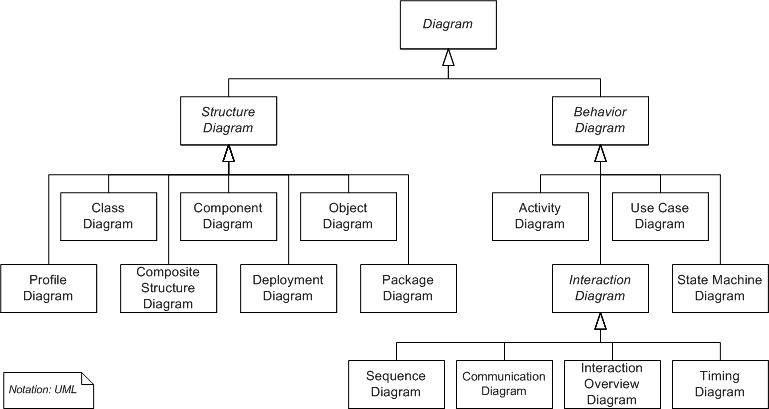
UML 2.2 has 14 types of diagrams divided into two categories. Seven diagram types represent structural information, and the other seven represent general types of behavior, including four that represent different aspects of interactions. These diagrams can be categorized hierarchically as shown in the following class diagram:
UML does not restrict UML element types to a certain diagram type. In general, every UML element may appear on almost all types of diagrams; this flexibility has been partially restricted in UML 2.0. UML profiles may define additional diagram types or extend existing diagrams with additional notations.
In keeping with the tradition of engineering drawings, a comment or note explaining usage, constraint, or intent is allowed in a UML diagram.
Structure diagrams
Structure diagrams emphasize the things that must be present in the system being modeled. Since structure diagrams represent the structure they are used extensively in documenting the architecture of software systems.
Behaviour diagrams
Behavior diagrams emphasize what must happen in the system being modeled. Since behavior diagrams illustrate the behavior of a system, they are used extensively to describe the functionality of software systems.
Interaction diagrams
Interaction diagrams, a subset of behaviour diagrams, emphasize the flow of control and data among the things in the system being modeled:
The Protocol State Machine is a sub-variant of the State Machine. It may be used to model network communication protocols.
Meta modeling
The Object Management Group (OMG) has developed a metamodeling architecture to define the Unified Modeling Language (UML), called the Meta-Object Facility (MOF). The Meta-Object Facility is a standard for model-driven engineering, designed as a four-layered architecture, as shown in the image at right. It provides a meta-meta model at the top layer, called the M3 layer. This M3-model is the language used by Meta-Object Facility to build metamodels, called M2-models. The most prominent example of a Layer 2 Meta-Object Facility model is the UML metamodel, the model that describes the UML itself. These M2-models describe elements of the M1-layer, and thus M1-models. These would be, for example, models written in UML. The last layer is the M0-layer or data layer. It is used to describe runtime instance of the system.
Beyond the M3-model, the Meta-Object Facility describes the means to create and manipulate models and metamodels by defining CORBA interfaces that describe those operations. Because of the similarities between the Meta-Object Facility M3-model and UML structure models, Meta-Object Facility metamodels are usually modeled as UML class diagrams. A supporting standard of the Meta-Object Facility is XMI, which defines an XML-based exchange format for models on the M3-, M2-, or M1-Layer.
UML includes a set of graphic notation techniques to create visual models of software-intensive systems.
Overview
The Unified Modeling Language (UML) is used to specify, visualize, modify, construct and document the artifacts of an object-oriented software-intensive system under development. UML offers a standard way to visualize a system's architectural blueprints, including elements such as:
- activities
- actors
- business processes
- database schemas
- (logical) components
- programming language statements
- reusable software components.
UML combines techniques from data modeling (entity relationship diagrams), business modeling (work flows), object modeling, and component modeling. It can be used with all processes, throughout the software development life cycle, and across different implementation technologies.[3] UML has synthesized the notations of the Booch method, the Object-modeling technique (OMT) and Object-oriented software engineering (OOSE) by fusing them into a single, common and widely usable modeling language. UML aims to be a standard modeling language which can model concurrent and distributed systems. UML is a de facto industry standard, and is evolving under the auspices of the Object Management Group (OMG).
UML models may be automatically transformed to other representations (e.g. Java) by means of QVT-like transformation languages, supported by the OMG. UML is extensible, offering the following mechanisms for customization: profiles and stereotypes.
Software development methods
UML is not a development method by itself;[4] however, it was designed to be compatible with the leading object-oriented software development methods of its time (for example OMT, Booch method, Objectory). Since UML has evolved, some of these methods have been recast to take advantage of the new notations (for example OMT), and new methods have been created based on UML. The best known is IBM Rational Unified Process (RUP). There are many other UML-based methods like Abstraction Method, Dynamic Systems Development Method, and others, to achieve different objectives.
Modeling
It is important to distinguish between the UML model and the set of diagrams of a system. A diagram is a partial graphic representation of a system's model. The model also contains documentation that drive the model elements and diagrams (such as written use cases).
UML diagrams represent two different views of a system model:
- Static (or structural) view: emphasizes the static structure of the system using objects, attributes, operations and relationships. The structural view includes class diagrams and composite structure diagrams.
- Dynamic (or behavioral) view: emphasizes the dynamic behavior of the system by showing collaborations among objects and changes to the internal states of objects. This view includes sequence diagrams, activity diagrams and state machine diagrams.
UML models can be exchanged among UML tools by using the XMI interchange format.
Diagrams overview
UML 2.2 has 14 types of diagrams divided into two categories. Seven diagram types represent structural information, and the other seven represent general types of behavior, including four that represent different aspects of interactions. These diagrams can be categorized hierarchically as shown in the following class diagram:
UML does not restrict UML element types to a certain diagram type. In general, every UML element may appear on almost all types of diagrams; this flexibility has been partially restricted in UML 2.0. UML profiles may define additional diagram types or extend existing diagrams with additional notations.
In keeping with the tradition of engineering drawings, a comment or note explaining usage, constraint, or intent is allowed in a UML diagram.
Structure diagrams
Structure diagrams emphasize the things that must be present in the system being modeled. Since structure diagrams represent the structure they are used extensively in documenting the architecture of software systems.
- Class diagram: describes the structure of a system by showing the system's classes, their attributes, and the relationships among the classes.
- Component diagram: describes how a software system is split up into components and shows the dependencies among these components.
- Composite structure diagram: describes the internal structure of a class and the collaborations that this structure makes possible.
- Deployment diagram: describes the hardware used in system implementations and the execution environments and artifacts deployed on the hardware.
- Object diagram: shows a complete or partial view of the structure of a modeled system at a specific time.
- Package diagram: describes how a system is split up into logical groupings by showing the dependencies among these groupings.
- Profile diagram: operates at the metamodel level to show stereotypes as classes with the stereotype, and profiles as packages with the stereotype. The extension relation (solid line with closed, filled arrowhead) indicates what metamodel element a given stereotype is extending.
Behaviour diagrams
Behavior diagrams emphasize what must happen in the system being modeled. Since behavior diagrams illustrate the behavior of a system, they are used extensively to describe the functionality of software systems.
- Activity diagram: describes the business and operational step-by-step workflows of components in a system. An activity diagram shows the overall flow of control.
- UML state machine diagram: describes the states and state transitions of the system.
- Use case diagram: describes the functionality provided by a system in terms of actors, their goals represented as use cases, and any dependencies among those use cases.
Interaction diagrams
Interaction diagrams, a subset of behaviour diagrams, emphasize the flow of control and data among the things in the system being modeled:
- Communication diagram: shows the interactions between objects or parts in terms of sequenced messages. They represent a combination of information taken from Class, Sequence, and Use Case Diagrams describing both the static structure and dynamic behavior of a system.
- Interaction overview diagram: provides an overview in which the nodes represent communication diagrams.
- Sequence diagram: shows how objects communicate with each other in terms of a sequence of messages. Also indicates the lifespans of objects relative to those messages.
- Timing diagrams: a specific type of interaction diagram where the focus is on timing constraints.
The Protocol State Machine is a sub-variant of the State Machine. It may be used to model network communication protocols.
Meta modeling
The Object Management Group (OMG) has developed a metamodeling architecture to define the Unified Modeling Language (UML), called the Meta-Object Facility (MOF). The Meta-Object Facility is a standard for model-driven engineering, designed as a four-layered architecture, as shown in the image at right. It provides a meta-meta model at the top layer, called the M3 layer. This M3-model is the language used by Meta-Object Facility to build metamodels, called M2-models. The most prominent example of a Layer 2 Meta-Object Facility model is the UML metamodel, the model that describes the UML itself. These M2-models describe elements of the M1-layer, and thus M1-models. These would be, for example, models written in UML. The last layer is the M0-layer or data layer. It is used to describe runtime instance of the system.
Beyond the M3-model, the Meta-Object Facility describes the means to create and manipulate models and metamodels by defining CORBA interfaces that describe those operations. Because of the similarities between the Meta-Object Facility M3-model and UML structure models, Meta-Object Facility metamodels are usually modeled as UML class diagrams. A supporting standard of the Meta-Object Facility is XMI, which defines an XML-based exchange format for models on the M3-, M2-, or M1-Layer.
Thursday, May 14, 2009
Spiral Model
The spiral model is a software development process combining elements of both design and prototyping-in-stages, in an effort to combine advantages of top-down and bottom-up concepts. Also known as the spiral lifecycle model (or spiral development), it is a systems development method (SDM) used in information technology (IT). This model of development combines the features of the prototyping model and the waterfall model. The spiral model is intended for large, expensive and complicated projects.
History
The spiral model was defined by Barry Boehm in his 1986 article "A Spiral Model of Software Development and Enhancement". This model was not the first model to discuss iterative development, but it was the first model to explain why the iteration matters.[citation needed]
As originally envisioned, the iterations were typically 6 months to 2 years long. Each phase starts with a design goal and ends with the client (who may be internal) reviewing the progress thus far. Analysis and engineering efforts are applied at each phase of the project, with an eye toward the end goal of the project.
Steps
The steps in the spiral model iteration can be generalized as follows:
Applications
The spiral model is mostly used in large projects. For smaller projects, the concept of agile software development is becoming a viable alternative. The US military had adopted the spiral model for its Future Combat Systems program. The FCS project was canceled after six years (2003 - 2009), it had a 2 year iteration (spiral). FCS should have resulted in 3 consecutive prototypes (one prototype per spiral - every 2 years). It was canceled in May, 2009. The spiral model thus may suit small (up to $3M) software applications and not complicated ($3B) distributed, interoperable, system of systems.
Also it is reasonable to use the spiral model in projects where business goals are unstable but the architecture must be realized well enough to provide high loading and stress ability. For example, the Spiral Architecture Driven Development is the spiral based SDLC which shows the possible way how to reduce a risk of non effective architecture with the help of spiral model in conjunction with the best practices from other models.
History
The spiral model was defined by Barry Boehm in his 1986 article "A Spiral Model of Software Development and Enhancement". This model was not the first model to discuss iterative development, but it was the first model to explain why the iteration matters.[citation needed]
As originally envisioned, the iterations were typically 6 months to 2 years long. Each phase starts with a design goal and ends with the client (who may be internal) reviewing the progress thus far. Analysis and engineering efforts are applied at each phase of the project, with an eye toward the end goal of the project.
Steps
The steps in the spiral model iteration can be generalized as follows:
- The system requirements are defined in as much detail as possible. This usually involves interviewing a number of users representing all the external or internal users and other aspects of the existing system.
- A preliminary design is created for the new system. This phase is the most important part of "Spiral Model". In this phase all possible (and available) alternatives, which can help in developing a cost effective project are analyzed and strategies to use them are decided. This phase has been added specially in order to identify and resolve all the possible risks in the project development. If risks indicate any kind of uncertainty in requirements, prototyping may be used to proceed with the available data and find out possible solution in order to deal with the potential changes in the requirements.
- A first prototype of the new system is constructed from the preliminary design. This is usually a scaled-down system, and represents an approximation of the characteristics of the final product.
- A second prototype is evolved by a fourfold procedure:
- evaluating the first prototype in terms of its strengths, weaknesses, and risks;
- defining the requirements of the second prototype;
- planning and designing the second prototype;
- constructing and testing the second prototype.
Applications
The spiral model is mostly used in large projects. For smaller projects, the concept of agile software development is becoming a viable alternative. The US military had adopted the spiral model for its Future Combat Systems program. The FCS project was canceled after six years (2003 - 2009), it had a 2 year iteration (spiral). FCS should have resulted in 3 consecutive prototypes (one prototype per spiral - every 2 years). It was canceled in May, 2009. The spiral model thus may suit small (up to $3M) software applications and not complicated ($3B) distributed, interoperable, system of systems.
Also it is reasonable to use the spiral model in projects where business goals are unstable but the architecture must be realized well enough to provide high loading and stress ability. For example, the Spiral Architecture Driven Development is the spiral based SDLC which shows the possible way how to reduce a risk of non effective architecture with the help of spiral model in conjunction with the best practices from other models.