Pages

Wednesday, September 23, 2009

Hard Disk Drive

A hard disk drive (HDD) is a non-volatile, random access device for digital data. It features rotating rigid platters on a motor-driven spindle within a protective enclosure. Data is magnetically read and written on the platter by read/write heads that float on a film of air above the platters.

Introduced by IBM in 1956, hard disk drives have fallen in cost and physical size over the years while dramatically increasing capacity. Hard disk drives have been the dominant device for secondary storage of data in general purpose computers since the early 1960s. They have maintained this position because advances in their areal recording density have kept pace with the requirements for secondary storage. Today's HDDs operate on high-speed serial interfaces; i.e., serial ATA (SATA) or serial attached SCSI (SAS).

History
Hard disk drives were introduced in 1956 as data storage for an IBM accounting computer) and were developed for use with general purpose mainframe and mini computers.
Driven by areal density doubling every two to four years since their invention, HDDs have changed in many ways, a few highlights include:
Capacity per HDD increasing from 3.75 megabytes to greater than 1 terabyte, a greater than 270 thousand to 1 improvement.
Size of HDD decreasing from 87.9 cubic feet (a double wide refrigerator) to 0.002 cubic feet (2½-inch form factor, a pack of cards), a greater than 44 thousand to 1 improvement.
Price decreasing from about $15,000 per megabyte to less than $0.0001 per megabyte ($100/1 terabyte), a greater than 150 million to 1 improvement
Average access time decreasing from greater than 0.1 second to a few thousandths of a second, a greater than 40 to 1 improvement.
Market application expanding from general purpose computers to most computing applications including consumer applications.

Technology
Magnetic recording
HDDs record data by magnetizing ferromagnetic material directionally. Sequential changes in the direction of magnetization represent patterns of binary data bits. The data are read from the disk by detecting the transitions in magnetization and decoding the originally written data. Different encoding schemes, such as Modified Frequency Modulation, group code recording, run-length limited encoding, and others are used.
A typical HDD design consists of a spindle that holds flat circular disks called platters, onto which the data are recorded. The platters are made from a non-magnetic material, usually aluminum alloy or glass, and are coated with a shallow layer of magnetic material, typically 10–20 nm in depth—for reference, standard copy paper is 0.07–0.18 millimetre (70,000–180,000 nm)—with an outer layer of carbon for protection.
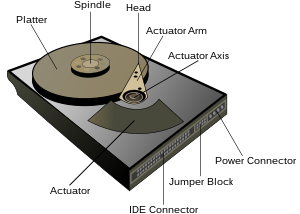
The platters are spun at speeds varying from 3,000 RPM in energy-efficient portable devices, to 15,000 RPM for high performance servers. Information is written to, and read from a platter as it rotates past devices called read-and-write heads that operate very close (tens of nanometers in new drives) over the magnetic surface. The read-and-write head is used to detect and modify the magnetization of the material immediately under it. In modern drives there is one head for each magnetic platter surface on the spindle, mounted on a common arm. An actuator arm (or access arm) moves the heads on an arc (roughly radially) across the platters as they spin, allowing each head to access almost the entire surface of the platter as it spins. The arm is moved using a voice coil actuator or in some older designs a stepper motor.
The magnetic surface of each platter is conceptually divided into many small sub-micrometer-sized magnetic regions referred to as magnetic domains. In older disk designs the regions were oriented horizontally and parallel to the disk surface, but beginning about 2005, the orientation was changed to perpendicular to allow for closer magnetic domain spacing. Due to the polycrystalline nature of the magnetic material each of these magnetic regions is composed of a few hundred magnetic grains. Magnetic grains are typically 10 nm in size and each form a single magnetic domain. Each magnetic region in total forms a magnetic dipole which generates a magnetic field.
For reliable storage of data, the recording material needs to resist self-demagnetization, which occurs when the magnetic domains repel each other. Magnetic domains written too densely together to a weakly magnetizable material will degrade over time due to physical rotation of one or more domains to cancel out these forces. The domains rotate sideways to a halfway position that weakens the readability of the domain and relieves the magnetic stresses. Older hard disks used iron(III) oxide as the magnetic material, but current disks use a cobalt-based alloy.
A write head magnetizes a region by generating a strong local magnetic field. Early HDDs used an electromagnet both to magnetize the region and to then read its magnetic field by using electromagnetic induction. Later versions of inductive heads included metal in Gap (MIG) heads and thin film heads. As data density increased, read heads using magnetoresistance (MR) came into use; the electrical resistance of the head changed according to the strength of the magnetism from the platter. Later development made use of spintronics; in these heads, the magnetoresistive effect was much greater than in earlier types, and was dubbed "giant" magnetoresistance (GMR). In today's heads, the read and write elements are separate, but in close proximity, on the head portion of an actuator arm. The read element is typically magneto-resistive while the write element is typically thin-film inductive.
The heads are kept from contacting the platter surface by the air that is extremely close to the platter; that air moves at or near the platter speed. The record and playback head are mounted on a block called a slider, and the surface next to the platter is shaped to keep it just barely out of contact. This forms a type of air bearing.
In modern drives, the small size of the magnetic regions creates the danger that their magnetic state might be lost because of thermal effects. To counter this, the platters are coated with two parallel magnetic layers, separated by a 3-atom layer of the non-magnetic element ruthenium, and the two layers are magnetized in opposite orientation, thus reinforcing each other. Another technology used to overcome thermal effects to allow greater recording densities is perpendicular recording, first shipped in 2005, and as of 2007 the technology was used in many HDDs.

Components
A typical hard drive has two electric motors, one to spin the disks and one to position the read/write head assembly. The disk motor has an external rotor attached to the platters; the stator windings are fixed in place. The actuator has a read-write head under the tip of its very end (near center); a thin printed-circuit cable connects the read-write head to the hub of the actuator. A flexible, somewhat U-shaped, ribbon cable, seen edge-on below and to the left of the actuator arm in the first image and more clearly in the second, continues the connection from the head to the controller board on the opposite side.
The head support arm is very light, but also stiff; in modern drives, acceleration at the head reaches 550 Gs.
The silver-colored structure at the upper left of the first image is the top plate of the permanent-magnet and moving coil motor that swings the heads to the desired position (it is shown removed in the second image). The plate supports a squat neodymium-iron-boron (NIB) high-flux magnet. Beneath this plate is the moving coil, often referred to as the voice coil by analogy to the coil in loudspeakers, which is attached to the actuator hub, and beneath that is a second NIB magnet, mounted on the bottom plate of the motor (some drives only have one magnet).
The voice coil itself is shaped rather like an arrowhead, and made of doubly coated copper magnet wire. The inner layer is insulation, and the outer is thermoplastic, which bonds the coil together after it is wound on a form, making it self-supporting. The portions of the coil along the two sides of the arrowhead (which point to the actuator bearing center) interact with the magnetic field, developing a tangential force that rotates the actuator. Current flowing radially outward along one side of the arrowhead and radially inward on the other produces the tangential force. If the magnetic field were uniform, each side would generate opposing forces that would cancel each other out. Therefore the surface of the magnet is half N pole, half S pole, with the radial dividing line in the middle, causing the two sides of the coil to see opposite magnetic fields and produce forces that add instead of canceling. Currents along the top and bottom of the coil produce radial forces that do not rotate the head.

Sunday, September 20, 2009

Computer Memory

In computing, memory refers to the state information of a computing system, as it is kept active in some physical structure. The term "memory" is used for the information in physical systems which are fast (i.e. RAM), as a distinction from physical systems which are slow to access (i.e. data storage). By design, the term "memory" refers to temporary state devices, whereas the term "storage" is reserved for permanent data. Advances in storage technology have blurred the distinction a bit —memory kept on what is conventionally a storage system is called "virtual memory".
Colloquially, computer memory refers to the physical devices used to store data or programs (sequences of instructions) on a temporary or permanent basis for use in an electronic digital computer. Computers represent information in binary code, written as sequences of 0s and 1s. Each binary digit (or "bit") may be stored by any physical system that can be in either of two stable states, to represent 0 and 1. Such a system is called bistable. This could be an on-off switch, an electrical capacitor that can store or lose a charge, a magnet with its polarity up or down, or a surface that can have a pit or not. Today, capacitors and transistors, functioning as tiny electrical switches, are used for temporary storage, and either disks or tape with a magnetic coating, or plastic discs with patterns of pits are used for long-term storage.
Computer memory is usually meant to refer to the semiconductor technology that is used to store information in electronic devices. Current primary computer memory makes use of integrated circuits consisting of silicon-based transistors. There are two main types of memory: volatile and non-volatile.

History
In the early 1940s, memory technology mostly permitted a capacity of a few bytes. The first programmable digital computer, the ENIAC, using thousands of octal-base radio vacuum tubes, could perform simple calculations involving 20 numbers of ten decimal digits which were held in the vacuum tube accumulators.
The next significant advance in computer memory was with acoustic delay line memory developed by J. Presper Eckert in the early 1940s. Through the construction of a glass tube filled with mercury and plugged at each end with a quartz crystal, delay lines could store bits of information within the quartz and transfer it through sound waves propagating through mercury. Delay line memory would be limited to a capacity of up to a few hundred thousand bits to remain efficient.
Two alternatives to the delay line, the Williams tube and Selectron tube, were developed in 1946, both using electron beams in glass tubes as means of storage. Using cathode ray tubes, Fred Williams would invent the Williams tube, which would be the first random access computer memory. The Williams tube would prove to be advantageous to the Selectron tube because of its greater capacity (the Selectron was limited to 256 bits, while the Williams tube could store thousands) and being less expensive. The Williams tube would nevertheless prove to be frustratingly sensitive to environmental disturbances.
Efforts began in the late 1940s to find non-volatile memory. Jay Forrester, Jan A. Rajchman and An Wang would be credited with the development of magnetic core memory, which would allow for recall of memory after power loss. Magnetic core memory would become the dominant form of memory until the development of transistor based memory in the late 1960s.

Volatile memory
Volatile memory is computer memory that requires power to maintain the stored information. Current semiconductor volatile memory technology is usually either static RAM (see SRAM) or dynamic RAM (see DRAM). Static RAM exhibits data remanence, but is still volatile, since all data is lost when memory is not powered. Whereas, dynamic RAM allows data to be leaked and disappear automatically without a refreshing. Upcoming volatile memory technologies that hope to replace or compete with SRAM and DRAM include Z-RAM, TTRAM and A-RAM.

Non-volatile memory
Non-volatile memory is computer memory that can retain the stored information even when not powered. Examples of non-volatile memory include read-only memory (see ROM), flash memory, most types of magnetic computer storage devices (e.g. hard disks, floppy discs and magnetic tape), optical discs, and early computer storage methods such as paper tape and punched cards.Upcoming non-volatile memory technologies include FeRAM, CBRAM, PRAM, SONOS, RRAM, Racetrack memory, NRAM and Millipede.

Thursday, September 17, 2009

Accelerated Graphics Port

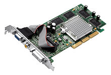
The Accelerated Graphics Port (often shortened to AGP) is a high-speed point-to-point channel for attaching a video card to a computer's motherboard, primarily to assist in the acceleration of 3D computer graphics. Since 2004, AGP has been progressively phased out in favor of PCI Express. As of mid-2009, PCIe cards dominate the market, but new AGP cards and motherboards are still available for purchase, though OEM driver support is minimal.

Advantages over PCI
As computers became increasingly graphically oriented, successive generations of graphics adapters began to push the limits of PCI, a bus with shared bandwidth. This led to the development of AGP, a "bus" dedicated to graphics adapters.
The primary advantage of AGP over PCI is that it provides a dedicated pathway between the slot and the processor rather than sharing the PCI bus. In addition to a lack of contention for the bus, the point-to-point connection allows for higher clock speeds. AGP also uses sideband addressing, meaning that the address and data buses are separated so the entire packet does not need to be read to get addressing information. This is done by adding eight extra 8-bit buses which allow the graphics controller to issue new AGP requests and commands at the same time with other AGP data flowing via the main 32 address/data (AD) lines. This results in improved overall AGP data throughput.
In addition, to load a texture, a PCI graphics card must copy it from the system's RAM into the card's framebuffer, whereas an AGP card is capable of reading textures directly from system RAM using the Graphics Address Remapping Table (GART). GART reapportions main memory as needed for texture storage, allowing the graphics card to access them directly. The maximum amount of system memory available to AGP is defined as the AGP aperture.
The two main reasons graphics cards with the PCI interface are still produced are that, first, they can be used in nearly any PC; because while some motherboards with built-in graphics adapters lack an AGP slot, few, if any, modern desktop PCs lack PCI slots. Secondly, a user with an appropriate operating system can use several PCI graphics cards (or several PCI graphics cards in combination with one AGP card) simultaneously — to give many different video outputs (for the use of many screens). This is almost impossible with AGP 1.0 and AGP 2.0 cards, because they do not support more than one AGP Master (video card) per AGP Target (chipset interface). AGP 3.0 does support more than one AGP Master per AGP Target, but nonetheless few PC motherboards are equipped with more than one AGP slot. Some server-class computers support having multiple AGP slots in a single system: the HP AlphaServer GS1280 has up to 6 AGP slots, the AlphaServer ES80 up to 4 AGP slots, and the AlphaServer ES47 up to 2 AGP slots.

History
The AGP slot first appeared on x86 compatible system boards based on Socket 7 Intel P5 Pentium and Slot 1 P6 Pentium II processors. Intel introduced AGP support with the i440LX Slot 1 chipset on the 26th of August 1997 and a flood of products followed from all the major system board vendors.
The first Socket 7 chipsets to support AGP were the VIA Apollo VP3, SiS 5591/5592, and the ALI Aladdin V. Intel never released an AGP-equipped Socket 7 chipset. FIC demonstrated the first Socket 7 AGP system board in November 1997 as the FIC PA-2012 based on the VIA Apollo VP3 chipset, followed very quickly by the EPoX P55-VP3 also based on the VIA VP3 chipset which was first to market.
Early video chipsets featuring AGP support included the Rendition Vérité V2200, 3dfx Voodoo Banshee, Nvidia RIVA 128, 3Dlabs PERMEDIA 2, Intel i740, ATI Rage series, Matrox Millennium II, and S3 ViRGE GX/2. Some early AGP boards used graphics processors built around PCI and were simply bridged to AGP. This resulted in the cards benefiting little from the new bus, with the only improvement used being the 66 MHz bus clock, with its resulting doubled bandwidth over PCI, and bus exclusivity. Examples of such cards were the Voodoo Banshee, Vérité V2200, Millennium II, and S3 ViRGE GX/2. Intel's i740 was explicitly designed to exploit the new AGP feature set. In fact it was designed to texture only from AGP memory, making PCI versions of the board difficult to implement (local board RAM had to emulate AGP memory.)

Microsoft first introduced AGP support into Windows 95 OEM Service Release 2 (OSR2 version 1111 or 950B) via the USB SUPPLEMENT to OSR2 patch. After applying the patch the Windows 95 system became Windows 95 version 4.00.950 B. The first Windows NT-based operating system to receive AGP support was Windows NT 4.0 with service pack 3, introduced in 1997. Linux support for AGP enhanced fast data transfers was first added in 1999 with the implementation of the AGPgart kernel module.

Compatibility
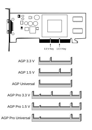
Compatibility, AGP Keys on card (top), on slot (bottom)

AGP cards are backward and forward compatible within limits. 1.5 V-only keyed cards will not go into 3.3 V slots and vice versa, though "Universal" slots exist which accept either type of card. AGP Pro cards will not fit into standard slots, but standard AGP cards will work in a Pro slot. Some cards, like Nvidia's GeForce 6 series (except the 6200) or ATI's Radeon X800 series, only have keys for 1.5 V to prevent them from being installed in older mainboards without 1.5 V support. Some of the last modern cards with 3.3 V support were the Nvidia GeForce FX series (FX 5200, FX 5500, FX 5700, some FX 5800, FX 5900 and some FX 5950) and the ATI Radeon 9500/9700/9800(R350) (but not 9600/9800(R360)). Some Geforce 6200 cards will function with AGP 1.0 (3.3v) slots.
It is important to check voltage compatibility as some cards incorrectly have dual notches and some motherboards incorrectly have fully open slots. Furthermore, some poorly designed older 3.3 V cards incorrectly have the 1.5 V key. Inserting a card into a slot that does not support the correct signaling voltage may cause damage.
Motherboard slots with both 3.3 V and 1.5 V keys do not exist.
There are some proprietary exceptions to this rule. For example, Apple Power Macintosh computers with the Apple Display Connector (ADC) have an extra connector which delivers power to the attached display. Additionally, moving cards between computers of various CPU architectures may not work due to firmware issues.

Use today
As of 2010, few new motherboards feature AGP slots. No new motherboard chipsets are equipped with AGP support, but motherboards continue to be produced with older chipsets that have AGP support. PCI Express allows for higher data transfer rates, has more robust full-duplex support, and also supports other devices.
All new graphics processors are designed for PCI-Express. To create AGP graphics cards, those chips require an additional PCIe to AGP bridge chip to convert PCIe signals to and from AGP signals. This incurs additional board costs due to the need for the additional bridge chip and for a separate AGP-designed circuit board.
Various manufacturers of graphics cards continue to produce AGP cards for the shrinking AGP user-base. The first bridged cards were the GeForce 6600 and ATI Radeon X800 XL boards, released during 2004-5. As of 2009, AGP cards from Nvidia have a ceiling of the GeForce 7 Series. As of 2009, DirectX 10-capable AGP cards from ATI include the Radeon HD 2400, 2600, 3650, and 3850 and the Radeon HD 4650, 4670.

Tuesday, September 15, 2009

PCI Express

PCI Express (Peripheral Component Interconnect Express), officially abbreviated as PCIe (or PCI-E, as it is commonly called), is a computer expansion card standard designed to replace the older PCI, PCI-X, and AGP standards. PCIe 3.0 is the latest standard for expansion cards that is available on mainstream personal computers.
PCI Express is used in consumer, server, and industrial applications, as a motherboard-level interconnect (to link motherboard-mounted peripherals) and as an expansion card interface for add-in boards. A key difference between PCIe and earlier buses is a topology based on point-to-point serial links, rather than a shared parallel bus architecture.
The PCIe electrical interface is also used in a variety of other standards, most notably the ExpressCard laptop expansion card interface.
Conceptually, the PCIe bus can be thought of as a high-speed serial replacement of the older (parallel) PCI/PCI-X bus. At the software level, PCIe preserves compatibility with PCI; a PCIe device can be configured and used in legacy applications and operating systems which have no direct knowledge of PCIe's newer features (though PCIe cards cannot be inserted into PCI slots). In terms of bus protocol, PCIe communication is encapsulated in packets. The work of packetizing and depacketizing data and status-message traffic is handled by the transaction layer of the PCIe port (described later). Radical differences in electrical signaling and bus protocol require the use of a different mechanical form factor and expansion connectors (and thus, new motherboards and new adapter boards).

Architecture
PCIe, unlike previous PC expansion standards, is structured around point-to-point serial links, a pair of which (one in each direction) make up a lane; rather than a shared parallel bus. These lanes are routed by a hub on the main-board acting as a crossbar switch. This dynamic point-to-point behavior allows more than one pair of devices to communicate with each other at the same time. In contrast, older PC interfaces had all devices permanently wired to the same bus; therefore, only one device could send information at a time. This format also allows channel grouping, where multiple lanes are bonded to a single device pair in order to provide higher bandwidth.
The number of lanes is negotiated during power-up or explicitly during operation. By making the lane count flexible, a single standard can provide for the needs of high-bandwidth cards (e.g., graphics, 10 Gigabit Ethernet and multiport Gigabit Ethernet cards) while being economical for less demanding cards.
Unlike preceding PC expansion interface standards, PCIe is a network of point-to-point connections. This removes the need for bus arbitration or waiting for the bus to be free, and enables full duplex communication. While standard PCI-X (133 MHz 64 bit) and PCIe ×4 have roughly the same data transfer rate, PCIe ×4 will give better performance if multiple device pairs are communicating simultaneously or if communication between a single device pair is bidirectional.
Format specifications are maintained and developed by the PCI-SIG (PCI Special Interest Group), a group of more than 900 companies that also maintain the Conventional PCI specifications.

Interconnect
PCIe devices communicate via a logical connection called an interconnect or link. A link is a point-to-point communication channel between 2 PCIe ports, allowing both to send/receive ordinary PCI-requests (configuration read/write, I/O read/write, memory read/write) and interrupts (INTx, MSI, MSI-X). At the physical level, a link is composed of 1 or more lanes. Low-speed peripherals (such as an 802.11 Wi-Fi card) use a single-lane (×1) link, while a graphics adapter typically uses a much wider (and thus, faster) 16-lane link.

Lane
A lane is composed of a transmit and receive pair of differential lines. Each lane is composed of 4 wires or signal paths, meaning conceptually, each lane is a full-duplex byte stream, transporting data packets in 8 bit 'byte' format, between endpoints of a link, in both directions simultaneously. Physical PCIe slots may contain from one to thirty-two lanes, in powers of two (1, 2, 4, 8, 16 and 32). Lane counts are written with an × prefix (e.g., ×16 represents a sixteen-lane card or slot), with ×16 being the largest size in common use.

Serial Bus
The bonded serial format was chosen over a traditional parallel format due to the phenomenon of timing skew. Timing skew is a direct result of the limitations imposed by the speed of an electrical signal traveling down a wire, which it does at the finite speed of electricity. Because signal paths across an interface have different finite lengths, parallel signals transmitted simultaneously arrive at their destinations at slightly different times. When the interface clock rate increases to the point where the wavelength of a single bit is less than the smallest difference between path lengths, the bits of a single word do not arrive at their destination simultaneously, making parallel recovery of the word difficult. Thus, the speed of the electrical signal, combined with the difference in length between the longest and shortest path in a parallel interconnect, leads to a naturally imposed maximum bandwidth. Serial channel bonding avoids this issue by not requiring the bits to arrive simultaneously. PCIe is just one example of a general trend away from parallel buses to serial interconnects. Other examples include Serial ATA, USB, SAS, FireWire and RapidIO. Multichannel serial design increases flexibility by allowing slow devices to be allocated fewer lanes than fast devices.