Pages

Wednesday, December 16, 2009

Wi-Fi

Wi-Fi (pronounced /ˈwaɪfaɪ/) is a trademark of the Wi-Fi Alliance. It is not a technical term. However, the Alliance has generally enforced its use to describe only a narrow range of connectivity technologies including wireless local area network (WLAN) based on the IEEE 802.11 standards, device to device connectivity [such as Wi-Fi Peer to Peer AKA Wi-Fi Direct], and a range of technologies that support PAN, LAN and even WAN connections. Derivative terms, such as Super Wi-Fi, coined by the U.S. Federal Communications Commission (FCC) to describe proposed networking in the former UHF TV band in the US, may or may not be sanctioned by the Alliance. As of November 2010 this was very unclear.
The technical term "IEEE 802.11" has been used interchangeably with Wi-Fi, however Wi-Fi has become a superset of IEEE 802.11 over the past few years. Wi-Fi is used by over 700 million people, there are over 750,000 hotspots (places with Wi-Fi Internet connectivity) around the world, and about 800 million new Wi-Fi devices every year. Wi-Fi products that complete the Wi-Fi Alliance interoperability certification testing successfully can use the Wi-Fi CERTIFIED designation and trademark.

Not every Wi-Fi device is submitted for certification to the Wi-Fi Alliance. The lack of Wi-Fi certification does not necessarily imply a device is incompatible with Wi-Fi devices/protocols. If it is compliant or partly compatible the Wi-Fi Alliance may not object to its description as a Wi-Fi device though technically only the CERTIFIED designation carries their approval.
Wi-Fi certified and compliant devices are installed in many personal computers, video game consoles, MP3 players, smartphones, printers, digital cameras, and laptop computers.
This article focuses on the certification and approvals process and the general growth of wireless networking under the Wi-Fi Alliance certified protocols. For more on the technologies see the appropriate articles with IEEE, ANSI, IETF , W3 and ITU prefixes (acronyms for the accredited standards organizations that have created formal technology standards for the protocols by which devices communicate). Non-Wi-Fi-Alliance wireless technologies intended for fixed points such as Motorola Canopy are usually described as fixed wireless. Non-Wi-Fi-Alliance wireless technologies intended for mobile use are usually described as 3G, 4G or 5G reflecting their origins and promotion by telephone/cell companies.

Wi-Fi certification
Wi-Fi technology builds on IEEE 802.11 standards. The IEEE develops and publishes some of these standards, but does not test equipment for compliance with them. The non-profit Wi-Fi Alliance formed in 1999 to fill this void — to establish and enforce standards for interoperability and backward compatibility, and to promote wireless local-area-network technology. As of 2010 the Wi-Fi Alliance consisted of more than 375 companies from around the world. Manufacturers with membership in the Wi-Fi Alliance, whose products pass the certification process, gain the right to mark those products with the Wi-Fi logo.
Specifically, the certification process requires conformance to the IEEE 802.11 radio standards, the WPA and WPA2 security standards, and the EAP authentication standard. Certification may optionally include tests of IEEE 802.11 draft standards, interaction with cellular-phone technology in converged devices, and features relating to security set-up, multimedia, and power-saving.
Most recently, a new security standard, Wi-Fi Protected Setup, allows embedded devices with limited graphical user interface to connect to the Internet with ease. Wi-Fi Protected Setup has 2 configurations: The Push Button configuration and the PIN configuration. These embedded devices are also called The Internet of Things and are low-power, battery-operated embedded systems. A number of Wi-Fi manufacturers design chips and modules for embedded Wi-Fi, such as GainSpan.

The name Wi-Fi
The term Wi-Fi suggests Wireless Fidelity, resembling the long-established audio-equipment classification term high fidelity (in use since the 1930s) or Hi-Fi (used since 1950). Even the Wi-Fi Alliance itself has often used the phrase Wireless Fidelity in its press releases and documents; the term also appears in a white paper on Wi-Fi from ITAA. However, based on Phil Belanger's statement, the term Wi-Fi was never supposed to mean anything at all.
The term Wi-Fi, first used commercially in August 1999, was coined by a brand-consulting firm called Interbrand Corporation that the Alliance had hired to determine a name that was "a little catchier than 'IEEE 802.11b Direct Sequence'". Belanger also stated that Interbrand invented Wi-Fi as a play on words with Hi-Fi, and also created the yin-yang-style Wi-Fi logo.
The Wi-Fi Alliance initially used an advertising slogan for Wi-Fi, "The Standard for Wireless Fidelity", but later removed the phrase from their marketing. Despite this, some documents from the Alliance dated 2003 and 2004 still contain the term Wireless Fidelity. There was no official statement related to the dropping of the term.
The yin-yang logo indicates the certification of a product for interoperability.

Internet access
A roof-mounted Wi-Fi antenna
A Wi-Fi enabled device such as a personal computer, video game console, smartphone or digital audio player can connect to the Internet when within range of a wireless network connected to the Internet. The coverage of one or more (interconnected) access points — called hotspots — can comprise an area as small as a few rooms or as large as many square miles. Coverage in the larger area may depend on a group of access points with overlapping coverage. Wi-Fi technology has been used in wireless mesh networks, for example, in London, UK.
In addition to private use in homes and offices, Wi-Fi can provide public access at Wi-Fi hotspots provided either free-of-charge or to subscribers to various commercial services. Organizations and businesses - such as those running airports, hotels and restaurants - often provide free-use hotspots to attract or assist clients. Enthusiasts or authorities who wish to provide services or even to promote business in selected areas sometimes provide free Wi-Fi access. As of 2008 more than 300 metropolitan-wide Wi-Fi (Muni-Fi) projects had started. As of 2010 the Czech Republic had 1150 Wi-Fi based wireless Internet service providers.
Routers that incorporate a digital subscriber line modem or a cable modem and a Wi-Fi access point, often set up in homes and other premises, can provide Internet access and internetworking to all devices connected (wirelessly or by cable) to them. With the emergence of MiFi and WiBro (a portable Wi-Fi router) people can easily create their own Wi-Fi hotspots that connect to Internet via cellular networks. Now many mobile phones can also create wireless connections via tethering on iPhone, Android, Symbian, and WinMo.
One can also connect Wi-Fi devices in ad-hoc mode for client-to-client connections without a router. Wi-Fi also connects places that would traditionally not have network access, for example bathrooms, kitchens and garden sheds.

City-wide Wi-Fi
Further information: Municipal wireless network
An outdoor Wi-Fi access point in Minneapolis

An outdoor Wi-Fi access point in Toronto

In the early 2000s, many cities around the world announced plans for city-wide Wi-Fi networks. This proved to be much more difficult than their promoters initially envisioned with the result that most of these projects were either canceled or placed on indefinite hold. A few were successful, for example in 2005, Sunnyvale, California became the first city in the United States to offer city-wide free Wi-Fi, and Minneapolis has generated $1.2 million profit annually for their provider.
In May, 2010, London, UK Mayor Boris Johnson pledged London-wide Wi-Fi by 2012. Both the City of London, UK and Islington already have extensive outdoor Wi-Fi coverage.

Campus-wide Wi-Fi
Carnegie Mellon University built the first wireless Internet network in the world at their Pittsburgh campus in 1994, long before Wi-Fi branding originated in 1999. Many traditional college campuses provide at least partial wireless Wi-Fi Internet coverage.
Drexel University in Philadelphia made history by becoming the United State's first major university to offer completely wireless Internet access across the entire campus in 2000.

Direct computer-to-computer communications
Wi-Fi also allows communications directly from one computer to another without the involvement of an access point. This is called the ad-hoc mode of Wi-Fi transmission. This wireless ad-hoc network mode has proven popular with multiplayer handheld game consoles, such as the Nintendo DS, digital cameras, and other consumer electronics devices.
Similarly, the Wi-Fi Alliance promotes a pending specification called Wi-Fi Direct for file transfers and media sharing through a new discovery- and security-methodology.

Future directions
As of 2010 Wi-Fi technology has spread widely within business and industrial sites. In business environments, just like other environments, increasing the number of Wi-Fi access points provides network redundancy, support for fast roaming and increased overall network-capacity by using more channels or by defining smaller cells. Wi-Fi enables wireless voice-applications (VoWLAN or WVOIP). Over the years, Wi-Fi implementations have moved toward "thin" access points, with more of the network intelligence housed in a centralized network appliance, relegating individual access points to the role of "dumb" transceivers. Outdoor applications may utilize mesh topologies.

Saturday, December 12, 2009

Bluetooth

Bluetooth is a proprietary open wireless technology standard for exchanging data over short distances (using short wavelength radio transmissions) from fixed and mobile devices, creating personal area networks (PANs) with high levels of security. Created by telecoms vendor Ericsson in 1994, it was originally conceived as a wireless alternative to RS-232 data cables. It can connect several devices, overcoming problems of synchronization. Today Bluetooth is managed by the Bluetooth Special Interest Group.

Name and logo
The word Bluetooth is an anglicised version of the Scandinavian Blåtand/Blåtann, the epithet of the tenth-century king Harald I of Denmark and parts of Norway who united dissonant Danish tribes into a single kingdom. The implication is that Bluetooth does the same with communications protocols, uniting them into one universal standard.
The Bluetooth logo is a bind rune merging the Younger Futhark runes Hagall and Bjarkan, Harald's initials.

Implementation
Bluetooth uses a radio technology called frequency-hopping spread spectrum, which chops up the data being sent and transmits chunks of it on up to 79 bands (1 MHz each) in the range 2402-2480 MHz. This range is in the globally unlicensed Industrial, Scientific and Medical (ISM) 2.4 GHz short-range radio frequency band.
Originally Gaussian frequency-shift keying (GFSK) modulation was the only modulation scheme available; subsequently, since the introduction of Bluetooth 2.0+EDR, π/4-DQPSK and 8DPSK modulation may also be used between compatible devices. Devices functioning with GFSK are said to be operating in basic rate (BR) mode where a gross data rate of 1 Mbit/s is possible. The term enhanced data rate (EDR) is used to describe π/4-DPSK and 8DPSK schemes, each giving 2 and 3 Mbit/s respectively. The combination of these (BR and EDR) modes in Bluetooth radio technology is classified as a "BR/EDR radio".
Bluetooth is a packet-based protocol with a master-slave structure. One master may communicate with up to 7 slaves in a piconet; all devices share the master's clock. Packet exchange is based on the basic clock, defined by the master, which ticks at 312.5 µs intervals. Two clock ticks make up a slot of 625 µs; two slots make up a slot pair of 1250 µs. In the simple case of single-slot packets the master transmits in even slots and receives in odd slots; the slave, conversely, receives in even slots and transmits in odd slots. Packets may be 1, 3 or 5 slots long but in all cases the master transmit will begin in even slots and the slave transmit in odd slots.
Bluetooth provides a secure way to connect and exchange information between devices such as faxes, mobile phones, telephones, laptops, personal computers, printers, Global Positioning System (GPS) receivers, digital cameras, and video game consoles.
The Bluetooth specifications are developed and licensed by the Bluetooth Special Interest Group (SIG). The Bluetooth SIG consists of more than 13,000 companies in the areas of telecommunication, computing, networking, and consumer electronics.
To be marketed as a Bluetooth device, it must be qualified to standards defined by the SIG.

Communication and connection
A master Bluetooth device can communicate with up to seven devices in a piconet. The devices can switch roles, by agreement, and the slave can become the master at any time.
At any given time, data can be transferred between the master and one other device (except for the little-used broadcast mode). The master chooses which slave device to address; typically, it switches rapidly from one device to another in a round-robin fashion.
The Bluetooth Core Specification provides for the connection of two or more piconets to form a scatternet, in which certain devices serve as bridges, simultaneously playing the master role in one piconet and the slave role in another.
Many USB Bluetooth adapters or "dongles" are available, some of which also include an IrDA adapter. Older (pre-2003) Bluetooth dongles, however, have limited capabilities, offering only the Bluetooth Enumerator and a less-powerful Bluetooth Radio incarnation. Such devices can link computers with Bluetooth with a distance of 100 meters, but they do not offer much in the way of services that modern adapters do.

Uses
Bluetooth is a standard wire-replacement communications protocol primarily designed for low power consumption, with a short range (power-class-dependent: 100 m, 10 m and 1 m, but ranges vary in practice; see table below) based on low-cost transceiver microchips in each device. Because the devices use a radio (broadcast) communications system, they do not have to be in line of sight of each other.
In most cases the effective range of class 2 devices is extended if they connect to a class 1 transceiver, compared to a pure class 2 network. This is accomplished by the higher sensitivity and transmission power of Class 1 devices.
While the Bluetooth Core Specification does mandate minimums for range, the range of the technology is application specific and is not limited. Manufacturers may tune their implementations to the range needed to support individual use cases.

Bluetooth profiles
To use Bluetooth wireless technology, a device must be able to interpret certain Bluetooth profiles, which are definitions of possible applications and specify general behaviors that Bluetooth enabled devices use to communicate with other Bluetooth devices. There are a wide range of Bluetooth profiles that describe many different types of applications or use cases for devices.
List of Applications

  • A typical Bluetooth mobile phone headset.
  • Wireless control of and communication between a mobile phone and a handsfree headset. This was one of the earliest applications to become popular.
  • Wireless networking between PCs in a confined space and where little bandwidth is required.
  • Wireless communication with PC input and output devices, the most common being the mouse, keyboard and printer.
  • Transfer of files, contact details, calendar appointments, and reminders between devices with OBEX.
  • Replacement of traditional wired serial communications in test equipment, GPS receivers, medical equipment, bar code scanners, and traffic control devices.
  • For controls where infrared was traditionally used.
  • For low bandwidth applications where higher USB bandwidth is not required and cable-free connection desired.
  • Sending small advertisements from Bluetooth-enabled advertising hoardings to other, discoverable, Bluetooth devices.
  • Wireless bridge between two Industrial Ethernet (e.g., PROFINET) networks.
  • Three seventh-generation game consoles, Nintendo's Wii and Sony's PlayStation 3 and PSP Go, use Bluetooth for their respective wireless controllers.
  • Dial-up internet access on personal computers or PDAs using a data-capable mobile phone as a wireless modem like Novatel mifi.
  • Short range transmission of health sensor data from medical devices to mobile phone, set-top box or dedicated telehealth devices.
  • Allowing a DECT phone to ring and answer calls on behalf of a nearby cell phone
  • Real-time location systems (RTLS), are used to track and identify the location of objects in real-time using “Nodes” or “tags” attached to, or embedded in the objects tracked, and “Readers” that receive and process the wireless signals from these tags to determine their locations
  • Tracking livestock and detainees. According to a leaked diplomatic cable, King Abdullah of Saudi Arabia suggested "implanting detainees with an electronic chip containing information about them and allowing their movements to be tracked with Bluetooth. This was done with horses and falcons, the King said."

Monday, December 7, 2009

Universal Serial Bus

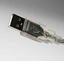
Universal Serial Bus (USB) is a specification to establish communication between devices and a host controller (usually personal computers), developed and invented by Ajay Bhatt while working for Intel. USB has effectively replaced a variety of interfaces such as serial and parallel ports.
USB can connect computer peripherals such as mice, keyboards, digital cameras, printers, personal media players, flash drives, Network Adapters, and external hard drives. For many of those devices, USB has become the standard connection method.
USB was designed for personal computers, but it has become commonplace on other devices such as smartphones, PDAs and video game consoles, and as a power cord. As of 2008, there are about 2 billion USB devices sold per year, and approximately 6 billion total sold to date.

History
The USB is a standard for peripheral devices. It began development in 1994 by a group of seven companies: Compaq, DEC, IBM, Intel, Microsoft, NEC and Nortel. USB was intended to make it fundamentally easier to connect external devices to PCs by replacing the multitude of connectors at the back of PCs, addressing the usability issues of existing interfaces, and simplifying software configuration of all devices connected to USB, as well as permitting greater bandwidths for external devices. The first silicon for USB was made by Intel in 1995.
The USB 1.0 specification was introduced in January 1996. The original USB 1.0 specification had a data transfer rate of 12 Mbit/s. The first widely used version of USB was 1.1, which was released in September 1998. It allowed for a 12 Mbit/s data rate for higher-speed devices such as disk drives, and a lower 1.5 Mbit/s rate for low bandwidth devices such as joysticks.
The USB 2.0 specification was released in April 2000 and was standardized by the USB-IF at the end of 2001. Hewlett-Packard, Intel, Lucent Technologies (now Alcatel-Lucent following its merger with Alcatel in 2006), NEC and Philips jointly led the initiative to develop a higher data transfer rate, with the resulting specification achieving 480 Mbit/s, a fortyfold increase over 12 Mbit/s for the original USB 1.0.

Overview
A USB system has an asymmetric design, consisting of a host, a multitude of downstream USB ports, and multiple peripheral devices connected in a tiered-star topology. Additional USB hubs may be included in the tiers, allowing branching into a tree structure with up to five tier levels. A USB host may have multiple host controllers and each host controller may provide one or more USB ports. Up to 127 devices, including hub devices if present, may be connected to a single host controller.
USB devices are linked in series through hubs. There always exists one hub known as the root hub, which is built into the host controller. So-called sharing hubs, which allow multiple computers to access the same peripheral device(s), also exist and work by switching access between PCs, either automatically or manually. Sharing hubs are popular in small-office environments. In network terms, they converge rather than diverge branches.
A physical USB device may consist of several logical sub-devices that are referred to as device functions. A single device may provide several functions, for example, a webcam (video device function) with a built-in microphone (audio device function). Such a device is called a compound device in which each logical device is assigned a distinctive address by the host and all logical devices are connected to a built-in hub to which the physical USB wire is connected. A host assigns one and only one device address to a function.


USB endpoints actually reside on the connected device: the channels to the host are referred to as pipes.
USB device communication is based on pipes (logical channels). A pipe is a connection from the host controller to a logical entity, found on a device, and named an endpoint. The term endpoint is occasionally incorrectly used for referring to the pipe. However, while an endpoint exists on the device permanently, a pipe is only formed when the host makes a connection to the endpoint. Therefore, when referring to a particular connection between a host and a USB device function, the term pipe should be used. A USB device can have up to 32 endpoints: 16 into the host controller and 16 out of the host controller. But, as one of the pipes is required to be of a bi-directional type (the default control pipe), and thus uses 2 endpoints, the theoretical maximum number of pipes is 31. USB devices seldom have this many endpoints.
There are two types of pipes: stream and message pipes depending on the type of data transfer.

  • isochronous transfers: at some guaranteed data rate (often, but not necessarily, as fast as possible) but with possible data loss (e.g. realtime audio or video).
  • interrupt transfers: devices that need guaranteed quick responses (bounded latency) (e.g. pointing devices and keyboards).
  • bulk transfers: large sporadic transfers using all remaining available bandwidth, but with no guarantees on bandwidth or latency (e.g. file transfers).
  • control transfers: typically used for short, simple commands to the device, and a status response, used, for example, by the bus control pipe number 0.

A stream pipe is a uni-directional pipe connected to a uni-directional endpoint that transfers data using an isochronous, interrupt, or bulk transfer. A message pipe is a bi-directional pipe connected to a bi-directional endpoint that is exclusively used for control data flow. An endpoint is built into the USB device by the manufacturer and therefore exists permanently. An endpoint of a pipe is addressable with tuple (device_address, endpoint_number) as specified in a TOKEN packet that the host sends when it wants to start a data transfer session. If the direction of the data transfer is from the host to the endpoint, an OUT packet (a specialization of a TOKEN packet) having the desired device address and endpoint number is sent by the host. If the direction of the data transfer is from the device to the host, the host sends an IN packet instead. If the destination endpoint is a uni-directional endpoint whose manufacturer's designated direction does not match the TOKEN packet (e.g., the manufacturer's designated direction is IN while the TOKEN packet is an OUT packet), the TOKEN packet will be ignored. Otherwise, it will be accepted and the data transaction can start. A bi-directional endpoint, on the other hand, accepts both IN and OUT packets.

Two USB receptacles on the front of a computer.

Endpoints are grouped into interfaces and each interface is associated with a single device function. An exception to this is endpoint zero, which is used for device configuration and which is not associated with any interface. A single device function composed of independently controlled interfaces is called a composite device. A composite device only has a single device address because the host only assigns a device address to a function.
When a USB device is first connected to a USB host, the USB device enumeration process is started. The enumeration starts by sending a reset signal to the USB device. The data rate of the USB device is determined during the reset signaling. After reset, the USB device's information is read by the host and the device is assigned a unique 7-bit address. If the device is supported by the host, the device drivers needed for communicating with the device are loaded and the device is set to a configured state. If the USB host is restarted, the enumeration process is repeated for all connected devices.
The host controller directs traffic flow to devices, so no USB device can transfer any data on the bus without an explicit request from the host controller. In USB 2.0, the host controller polls the bus for traffic, usually in a round-robin fashion. The slowest device connected to a controller sets the bandwidth of the interface. For SuperSpeed USB (defined since USB 3.0), connected devices can request service from host. Because there are two separate controllers in each USB 3.0 host, USB 3.0 devices will transmit and receive at USB 3.0 data rates regardless of USB 2.0 or earlier devices connected to that host. Operating data rates for them will be set in the legacy manner.

Tuesday, December 1, 2009

SCSI

Small Computer System Interface, or SCSI (pronounced scuzzy), is a set of standards for physically connecting and transferring data between computers and peripheral devices. The SCSI standards define commands, protocols, and electrical and optical interfaces. SCSI is most commonly used for hard disks and tape drives, but it can connect a wide range of other devices, including scanners and CD drives. The SCSI standard defines command sets for specific peripheral device types; the presence of "unknown" as one of these types means that in theory it can be used as an interface to almost any device, but the standard is highly pragmatic and addressed toward commercial requirements.
SCSI is an intelligent, peripheral, buffered, peer to peer interface. It hides the complexity of physical format. Every device attaches to the SCSI bus in a similar manner. Up to 8 or 16 devices can be attached to a single bus. There can be any number of hosts and peripheral devices but there should be at least one host. SCSI uses hand shake signals between devices, SCSI-1, SCSI-2 have the option of parity error checking. Starting with SCSI-U160 (part of SCSI-3) all commands and data are error checked by a CRC32 checksum. The SCSI protocol defines communication from host to host, host to a peripheral device, peripheral device to a peripheral device. However most peripheral devices are exclusively SCSI targets, incapable of acting as SCSI initiators—unable to initiate SCSI transactions themselves. Therefore peripheral-to-peripheral communications are uncommon, but possible in most SCSI applications. The Symbios Logic 53C810 chip is an example of a PCI host interface that can act as a SCSI target.

History
SCSI was derived from "SASI", the "Shugart Associates System Interface", developed c. 1978 and publicly disclosed in 1981. A SASI controller provided a bridge between a hard disk drive's low-level interface and a host computer, which needed to read blocks of data. SASI controller boards were typically the size of a hard disk drive and were usually physically mounted to the drive's chassis. SASI, which was used in mini- and early microcomputers, defined the interface as using a 50-pin flat ribbon connector which was adopted as the SCSI-1 connector. SASI is a fully compliant subset of SCSI-1 so that many, if not all, of the then existing SASI controllers were SCSI-1 compatible.
Larry Boucher is considered to be the "father" of SASI and SCSI due to his pioneering work first at Shugart Associates and then at Adaptec.
Until at least February 1982, ANSI developed the specification as "SASI" and "Shugart Associates System Interface;" however, the committee documenting the standard would not allow it to be named after a company. Almost a full day was devoted to agreeing to name the standard "Small Computer System Interface," which Boucher intended to be pronounced "sexy", but ENDL's Dal Allan pronounced the new acronym as "scuzzy" and that stuck.
A number of companies such as NCR Corporation, Adaptec and Optimem were early supporters of the SCSI standard. The NCR facility in Wichita, Kansas is widely thought to have developed the industry's first SCSI chip; it worked the first time.
The "small" part in SCSI is historical; since the mid-1990s, SCSI has been available on even the largest of computer systems.
Since its standardization in 1986, SCSI has been commonly used in the Amiga, Apple Macintosh and Sun Microsystems computer lines and PC server systems. Apple started using Parallel ATA (also known as IDE) for its low-end machines with the Macintosh Quadra 630 in 1994, and added it to its high-end desktops starting with the Power Macintosh G3 in 1997. Apple dropped on-board SCSI completely (in favor of IDE and FireWire) with the (Blue & White) Power Mac G3 in 1999. Sun has switched its lower end range to Serial ATA (SATA). SCSI has never been popular in the low-priced IBM PC world, owing to the lower cost and adequate performance of ATA hard disk standard. SCSI drives and even SCSI RAIDs became common in PC workstations for video or audio production.
Recent versions of SCSI — Serial Storage Architecture (SSA), SCSI-over-Fibre Channel Protocol (FCP), Serial Attached SCSI (SAS), Automation/Drive Interface − Transport Protocol (ADT), and USB Attached SCSI (UAS) — break from the traditional parallel SCSI standards and perform data transfer via serial communications. Although much of the documentation of SCSI talks about the parallel interface, most contemporary development effort is on serial SCSI. Serial SCSI has a number of advantages over parallel SCSI: faster data rates, hot swapping (some but not all parallel SCSI interfaces support it), and improved fault isolation. The primary reason for the shift to serial interfaces is the clock skew issue of high speed parallel interfaces, which makes the faster variants of parallel SCSI susceptible to problems caused by cabling and termination. Serial SCSI devices are more expensive than the equivalent parallel SCSI devices, but this is likely to change soon.
iSCSI preserves the basic SCSI paradigm, especially the command set, almost unchanged, through embedding of SCSI-3 over TCP/IP.
SCSI is popular on high-performance workstations and servers. RAIDs on servers almost always use SCSI hard disks, though a number of manufacturers offer SATA-based RAID systems as a cheaper option. Desktop computers and notebooks more typically use the ATA/IDE or the newer SATA interfaces for hard disks, and USB, eSATA, and FireWire connections for external devices.

SCSI interfaces
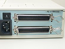
Two SCSI connectors

SCSI is available in a variety of interfaces. The first, still very common, was parallel SCSI (now also called SPI), which uses a parallel electrical bus design. As of 2008, SPI is being replaced by Serial Attached SCSI (SAS), which uses a serial design but retains other aspects of the technology. iSCSI drops physical implementation entirely, and instead uses TCP/IP as a transport mechanism. Many other interfaces which do not rely on complete SCSI standards still implement the SCSI command protocol.
SCSI interfaces have often been included on computers from various manufacturers for use under Microsoft Windows, Mac OS, Unix and Linux operating systems, either implemented on the motherboard or by the means of plug-in adaptors. With the advent of SAS and SATA drives, provision for SCSI on motherboards is being discontinued. A few companies still market SCSI interfaces for motherboards supporting PCIe and PCI-X.

Monday, November 23, 2009

Parallel ATA

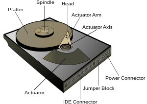
Parallel ATA (PATA), originally ATA, is an interface standard for the connection of storage devices such as hard disks, solid-state drives, floppy drives, and CD-ROM drives in computers. The standard is maintained by X3/INCITS committee. It uses the underlying AT Attachment (ATA) and AT Attachment Packet Interface (ATAPI) standards.
The current Parallel ATA standard is the result of a long history of incremental technical development, which began with the original AT Attachment interface, developed for use in early PC AT equipment. The ATA interface itself evolved in several stages from Western Digital's original Integrated Drive Electronics (IDE) interface. As a result, many near-synonyms for ATA/ATAPI and its previous incarnations exist, including abbreviations such as IDE which are still in common informal use. After the market introduction of Serial ATA in 2003, the original ATA was retroactively renamed Parallel ATA.
Parallel ATA only allows cable lengths up to 18 in (457 mm). Because of this length limit the technology normally appears as an internal computer storage interface. For many years ATA provided the most common and the least expensive interface for this application. By the beginning of 2007, it had largely been replaced by Serial ATA (SATA) in new systems.

History and terminology
The standard was originally conceived as "PC/AT Attachment" as its primary feature was a direct connection to the 16-bit ISA bus introduced with the IBM PC/AT. The name was shortened to "AT Attachment" to avoid possible trademark issues. It is not spelled out as "Advanced Technology" anywhere in current or recent versions of the specification; it is simply "AT Attachment".

Parallel ATA interface
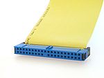
Until the introduction of Serial ATA, 40-pin connectors generally attached drives to a ribbon cable. Each cable has two or three connectors, one of which plugs into an adapter interfacing with the rest of the computer system. The remaining connector(s) plug into drives. Parallel ATA cables transfer data 16 bits at a time.
ATA's ribbon cables have had 40 wires for most of its history (44 conductors for the smaller form-factor version used for 2.5" drives — the extra four for power), but an 80-wire version appeared with the introduction of the Ultra DMA/33 (UDMA) mode. All of the additional wires in the new cable are ground wires, interleaved with the previously defined wires to reduce the effects of capacitive coupling between neighboring signal wires, reducing crosstalk. Capacitive coupling is more of a problem at higher transfer rates, and this change was necessary to enable the 66 megabytes per second (MB/s) transfer rate of UDMA4 to work reliably. The faster UDMA5 and UDMA6 modes also require 80-conductor cables.

Though the number of wires doubled, the number of connector pins and the pinout remain the same as 40-conductor cables, and the external appearance of the connectors is identical. Internally the connectors are different; the connectors for the 80-wire cable connect a larger number of ground wires to a smaller number of ground pins, while the connectors for the 40-wire cable connect ground wires to ground pins one-for-one. 80-wire cables usually come with three differently colored connectors (blue — controller, gray — slave drive, and black — master drive) as opposed to uniformly colored 40-wire cable's connectors (all black). The gray connector on 80-conductor cables has pin 28 CSEL not connected; making it the slave position for drives configured cable select.
Pin 20
In the ATA standard pin 20 is defined as (mechanical) key and is not used; i.e., this socket on the female connector is often obstructed, and a cable or drive connector with a pin in this position cannot be connected, making it impossible to plug in a connector the wrong way round. However, some flash memory drives can use pin 20 as VCC_in to power the drive without requiring a special power cable.
Pin 28
Pin 28 of the gray (slave/middle) connector of an 80 conductor cable is not attached to any conductor of the cable. It is attached normally on the black (master drive end) and blue (motherboard end) connectors.
Pin 34
Pin 34 is connected to ground inside the blue connector of an 80 conductor cable but not attached to any conductor of the cable. It is attached normally on the gray and black connectors. See page 315 of.

Sunday, November 15, 2009

Serial ATA

Serial ATA (SATA or Serial Advanced Technology Attachment) is a computer bus interface for connecting host bus adapters to mass storage devices such as hard disk drives and optical drives. Serial ATA was designed to replace the older ATA (AT Attachment) standard (also known as EIDE). It is able to use the same low level commands, but serial ATA host-adapters and devices communicate via a high-speed serial cable over two pairs of conductors. In contrast, the parallel ATA (the redesignation for the legacy ATA specifications) used 16 data conductors each operating at a much lower speed.

SATA offers several advantages over the older parallel ATA (PATA) interface: reduced cable-bulk and cost (reduced from 80 wires to seven), faster and more efficient data transfer, and hot swapping.
The SATA host adapter is integrated into almost all modern consumer laptop computers and desktop motherboards. As of 2009, SATA has replaced parallel ATA in most shipping consumer PCs. PATA remains in industrial and embedded applications dependent on CompactFlash storage although the new CFast storage standard will be based on SATA.

SATA specification bodies
Serial ATA industry compatibility specifications originate from The Serial ATA International Organization (aka. SATA-IO, serialata.org). The SATA-IO group collaboratively creates, reviews, ratifies, and publishes the interoperability specifications, the test cases, and plug-fests. As with many other industry compatibility standards, the SATA content ownership is transferred to other industry bodies: primarily the INCITS T13subcommittee ATA, the INCITS T10 subcommittee (SCSI); a subgroup of T10 responsible for SAS. The complete specification from SATA-IO. The remainder of this article will try to use the terminology and specifications of SATA-IO.
The SATA-IO succeeded in its mission of improving PATA. More than 1.1 billion SATA disk drives have been shipped from 2001 through 2008. SATA’s market share in the desktop PC market is 99% in 2008.

Features

Hotplug
The Serial ATA Spec includes logic for SATA device hotplugging. Devices and motherboards that meet the interoperability spec are capable of hot plugging.

Advanced Host Controller Interface
As their standard interface, SATA controllers use the AHCI (Advanced Host Controller Interface), allowing advanced features of SATA such as hotplug and native command queuing (NCQ). If AHCI is not enabled by the motherboard and chipset, SATA controllers typically operate in "IDE emulation" mode, which does not allow features of devices to be accessed if the ATA/IDE standard does not support them.
Windows device drivers that are labeled as SATA are often running in IDE emulation mode unless they explicitly state that they are AHCI mode, in RAID mode, or a mode provided by a proprietary driver and command set that was designed to allow access to SATA's advanced features before AHCI became popular. Modern versions of Microsoft Windows, FreeBSD, Linux with version 2.6.19 onward, as well as Solaris and OpenSolaris include support for AHCI, but older OSes such as Windows XP do not. Even in those instances a proprietary driver may have been created for a specific chipset, such as Intel's.

Sunday, November 8, 2009

Basic Computer Network Components

Basic hardware components
All networks are made up of basic hardware building blocks to interconnect network nodes, such as Network Interface Cards (NICs), Bridges, Hubs, Switches, and Routers. In addition, some method of connecting these building blocks is required, usually in the form of galvanic cable (most commonly Category 5 cable). Less common are microwave links (as in IEEE 802.12) or optical cable ("optical fiber").

Network interface cards
A network card, network adapter, or NIC (network interface card) is a piece of computer hardware designed to allow computers to communicate over a computer network. It provides physical access to a networking medium and often provides a low-level addressing system through the use of MAC addresses.
Each network interface card has its unique id. This is written on a chip which is mounted on the card.

Repeaters
A repeater is an electronic device that receives a signal, cleans it of unnecessary noise, regenerates it, and retransmits it at a higher power level, or to the other side of an obstruction, so that the signal can cover longer distances without degradation. In most twisted pair Ethernet configurations, repeaters are required for cable that runs longer than 100 meters. Repeaters work on the Physical Layer of the OSI model.

Hubs
A network hub contains multiple ports. When a packet arrives at one port, it is copied unmodified to all ports of the hub for transmission. The destination address in the frame is not changed to a broadcast address. It works on the Physical Layer of the OSI model..

Bridges
A network bridge connects multiple network segments at the data link layer (layer 2) of the OSI model. Bridges broadcast to all ports except the port on which the broadcast was received. However, bridges do not promiscuously copy traffic to all ports, as hubs do, but learn which MAC addresses are reachable through specific ports. Once the bridge associates a port and an address, it will send traffic for that address to that port only.
Bridges learn the association of ports and addresses by examining the source address of frames that it sees on various ports. Once a frame arrives through a port, its source address is stored and the bridge assumes that MAC address is associated with that port. The first time that a previously unknown destination address is seen, the bridge will forward the frame to all ports other than the one on which the frame arrived.
Bridges come in three basic types:

  • Local bridges: Directly connect local area networks (LANs)
  • Remote bridges: Can be used to create a wide area network (WAN) link between LANs. Remote bridges, where the connecting link is slower than the end networks, largely have been replaced with routers.
  • Wireless bridges: Can be used to join LANs or connect remote stations to LANs.


Switches
A network switch is a device that forwards and filters OSI layer 2 datagrams (chunks of data communication) between ports (connected cables) based on the MAC addresses in the packets. A switch is distinct from a hub in that it only forwards the frames to the ports involved in the communication rather than all ports connected. A switch breaks the collision domain but represents itself as a broadcast domain. Switches make forwarding decisions of frames on the basis of MAC addresses. A switch normally has numerous ports, facilitating a star topology for devices, and cascading additional switches. Some switches are capable of routing based on Layer 3 addressing or additional logical levels; these are called multi-layer switches. The term switch is used loosely in marketing to encompass devices including routers and bridges, as well as devices that may distribute traffic on load or by application content (e.g., a Web URL identifier).

Routers
A router is an internetworking device that forwards packets between networks by processing information found in the datagram or packet (Internet protocol information from Layer 3 of the OSI Model). In many situations, this information is processed in conjunction with the routing table (also known as forwarding table). Routers use routing tables to determine what interface to forward packets (this can include the "null" also known as the "black hole" interface because data can go into it, however, no further processing is done for said data).

Firewalls
Firewalls are the most important aspect of a network with respect to security. A firewalled system does not need every interaction or data transfer monitored by a human, as automated processes can be set up to assist in rejecting access requests from unsafe sources, and allowing actions from recognized ones. The vital role firewalls play in network security grows in parallel with the constant increase in 'cyber' attacks for the purpose of stealing/corrupting data, planting viruses, etc.

Sunday, November 1, 2009

Types of Computer Networks

Local Area Network
A local area network (LAN) is a network that connects computers and devices in a limited geographical area such as home, school, computer laboratory, office building, or closely positioned group of buildings. Each computer or device on the network is a node. Current wired LANs are most likely to be based on Ethernet technology, although new standards like ITU-T G.hn also provide a way to create a wired LAN using existing home wires (coaxial cables, phone lines and power lines).
All interconnected devices must understand the network layer (layer 3), because they are handling multiple subnets (the different colors). Those inside the library, which have only 10/100 Mbit/s Ethernet connections to the user device and a Gigabit Ethernet connection to the central router, could be called "layer 3 switches" because they only have Ethernet interfaces and must understand IP. It would be more correct to call them access routers, where the router at the top is a distribution router that connects to the Internet and academic networks' customer access routers.
The defining characteristics of LANs, in contrast to WANs (Wide Area Networks), include their higher data transfer rates, smaller geographic range, and no need for leased telecommunication lines. Current Ethernet or other IEEE 802.3 LAN technologies operate at speeds up to 10 Gbit/s. This is the data transfer rate. IEEE has projects investigating the standardization of 40 and 100 Gbit/s.

Personal area network
A personal area network (PAN) is a computer network used for communication among computer and different information technological devices close to one person. Some examples of devices that are used in a PAN are personal computers, printers, fax machines, telephones, PDAs, scanners, and even video game consoles. A PAN may include wired and wireless devices. The reach of a PAN typically extends to 10 meters. A wired PAN is usually constructed with USB and Firewire connections while technologies such as Bluetooth and infrared communication typically form a wireless PAN.

Home area network
A home area network (HAN) is a residential LAN which is used for communication between digital devices typically deployed in the home, usually a small number of personal computers and accessories, such as printers and mobile computing devices. An important function is the sharing of Internet access, often a broadband service through a CATV or Digital Subscriber Line (DSL) provider. It can also be referred to as an office area network (OAN).

Wide area network
A wide area network (WAN) is a computer network that covers a large geographic area such as a city, country, or spans even intercontinental distances, using a communications channel that combines many types of media such as telephone lines, cables, and air waves. A WAN often uses transmission facilities provided by common carriers, such as telephone companies. WAN technologies generally function at the lower three layers of the OSI reference model: the physical layer, the data link layer, and the network layer.

Campus network
A campus network is a computer network made up of an interconnection of local area networks (LAN's) within a limited geographical area. The networking equipments (switches, routers) and transmission media (optical fiber, copper plant, Cat5 cabling etc.) are almost entirely owned (by the campus tenant / owner: an enterprise, university, government etc.).
In the case of a university campus-based campus network, the network is likely to link a variety of campus buildings including; academic departments, the university library and student residence halls.

Metropolitan area network
A Metropolitan area network is a large computer network that usually spans a city or a large campus.

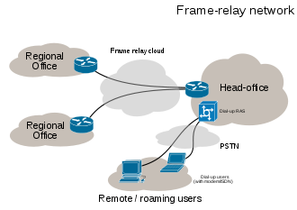
Sample EPN made of Frame relay WAN connections and dialup remote access.

Sample VPN used to interconnect 3 offices and remote users

Enterprise private network
An enterprise private network is a network build by an enterprise to interconnect various company sites, e.g., production sites, head offices, remote offices, shops, in order to share computer resources.

Virtual private network
A virtual private network (VPN) is a computer network in which some of the links between nodes are carried by open connections or virtual circuits in some larger network (e.g., the Internet) instead of by physical wires. The data link layer protocols of the virtual network are said to be tunneled through the larger network when this is the case. One common application is secure communications through the public Internet, but a VPN need not have explicit security features, such as authentication or content encryption. VPNs, for example, can be used to separate the traffic of different user communities over an underlying network with strong security features.
VPN may have best-effort performance, or may have a defined service level agreement (SLA) between the VPN customer and the VPN service provider. Generally, a VPN has a topology more complex than point-to-point.

Internetwork
An internetwork is the connection of two or more private computer networks via a common routing technology (OSI Layer 3) using routers. The Internet is an aggregation of many internetworks, hence its name was shortened to Internet.

Backbone network
A Backbone network (BBN) A backbone network or network backbone is part of a computer network infrastructure that interconnects various pieces of network, providing a path for the exchange of information between different LANs or subnetworks. A backbone can tie together diverse networks in the same building, in different buildings in a campus environment, or over wide areas. Normally, the backbone's capacity is greater than the networks connected to it.
A large corporation that has many locations may have a backbone network that ties all of the locations together, for example, if a server cluster needs to be accessed by different departments of a company that are located at different geographical locations. The pieces of the network connections (for example: ethernet, wireless) that bring these departments together is often mentioned as network backbone. Network congestion is often taken into consideration while designing backbones.
Backbone networks should not be confused with the Internet backbone.

Global Area Network
A Global Area Network (GAN) is a network used for supporting mobile communications across an arbitrary number of wireless LANs, satellite coverage areas, etc. The key challenge in mobile communications is handing off the user communications from one local coverage area to the next. In IEEE Project 802, this involves a succession of terrestrial wireless LANs.

Internet
The Internet is a global system of interconnected governmental, academic, corporate, public, and private computer networks. It is based on the networking technologies of the Internet Protocol Suite. It is the successor of the Advanced Research Projects Agency Network (ARPANET) developed by DARPA of the United States Department of Defense. The Internet is also the communications backbone underlying the World Wide Web (WWW).
Participants in the Internet use a diverse array of methods of several hundred documented, and often standardized, protocols compatible with the Internet Protocol Suite and an addressing system (IP addresses) administered by the Internet Assigned Numbers Authority and address registries. Service providers and large enterprises exchange information about the reachability of their address spaces through the Border Gateway Protocol (BGP), forming a redundant worldwide mesh of transmission paths.

Intranets and extranets
Intranets and extranets are parts or extensions of a computer network, usually a local area network.
An intranet is a set of networks, using the Internet Protocol and IP-based tools such as web browsers and file transfer applications, that is under the control of a single administrative entity. That administrative entity closes the intranet to all but specific, authorized users. Most commonly, an intranet is the internal network of an organization. A large intranet will typically have at least one web server to provide users with organizational information.
An extranet is a network that is limited in scope to a single organization or entity and also has limited connections to the networks of one or more other usually, but not necessarily, trusted organizations or entities—a company's customers may be given access to some part of its intranet—while at the same time the customers may not be considered trusted from a security standpoint. Technically, an extranet may also be categorized as a CAN, MAN, WAN, or other type of network, although an extranet cannot consist of a single LAN; it must have at least one connection with an external network.

Overlay network
An overlay network is a virtual computer network that is built on top of another network. Nodes in the overlay are connected by virtual or logical links, each of which corresponds to a path, perhaps through many physical links, in the underlying network.

A sample overlay network: IP over SONET over Optical

For example, many peer-to-peer networks are overlay networks because they are organized as nodes of a virtual system of links run on top of the Internet. The Internet was initially built as an overlay on the telephone network .
Overlay networks have been around since the invention of networking when computer systems were connected over telephone lines using modem, before any data network existed.
Nowadays the Internet is the basis for many overlaid networks that can be constructed to permit routing of messages to destinations specified by an IP address. For example, distributed hash tables can be used to route messages to a node having a specific logical address, whose IP address is known in advance.
Overlay networks have also been proposed as a way to improve Internet routing, such as through quality of service guarantees to achieve higher-quality streaming media. Previous proposals such as IntServ, DiffServ, and IP Multicast have not seen wide acceptance largely because they require modification of all routers in the network. On the other hand, an overlay network can be incrementally deployed on end-hosts running the overlay protocol software, without cooperation from Internet service providers. The overlay has no control over how packets are routed in the underlying network between two overlay nodes, but it can control, for example, the sequence of overlay nodes a message traverses before reaching its destination.
For example, Akamai Technologies manages an overlay network that provides reliable, efficient content delivery (a kind of multicast). Academic research includes End System Multicast and Overcast for multicast; RON (Resilient Overlay Network) for resilient routing; and OverQoS for quality of service guarantees, among others. A backbone network or network backbone is a part of computer network infrastructure that interconnects various pieces of network, providing a path for the exchange of information between different LANs or subnetworks. A backbone can tie together diverse networks in the same building, in different buildings in a campus environment, or over wide areas. Normally, the backbone's capacity is greater than the networks connected to it.

Monday, October 26, 2009

Microprocessors

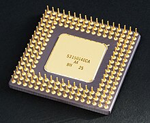
The introduction of the microprocessor in the 1970s significantly affected the design and implementation of CPUs. Since the introduction of the first commercially available microprocessor (the Intel 4004) in 1970 and the first widely used microprocessor (the Intel 8080) in 1974, this class of CPUs has almost completely overtaken all other central processing unit implementation methods. Mainframe and minicomputer manufacturers of the time launched proprietary IC development programs to upgrade their older computer architectures, and eventually produced instruction set compatible microprocessors that were backward-compatible with their older hardware and software. Combined with the advent and eventual vast success of the now ubiquitous personal computer, the term "CPU" is now applied almost exclusively to microprocessors.

Previous generations of CPUs were implemented as discrete components and numerous small integrated circuits (ICs) on one or more circuit boards. Microprocessors, on the other hand, are CPUs manufactured on a very small number of ICs; usually just one. The overall smaller CPU size as a result of being implemented on a single die means faster switching time because of physical factors like decreased gate parasitic capacitance. This has allowed synchronous microprocessors to have clock rates ranging from tens of megahertz to several gigahertz. Additionally, as the ability to construct exceedingly small transistors on an IC has increased, the complexity and number of transistors in a single CPU has increased dramatically. This widely observed trend is described by Moore's law, which has proven to be a fairly accurate predictor of the growth of CPU (and other IC) complexity to date.

While the complexity, size, construction, and general form of CPUs have changed drastically over the past sixty years, it is notable that the basic design and function has not changed much at all. Almost all common CPUs today can be very accurately described as von Neumann stored-program machines. As the aforementioned Moore's law continues to hold true, concerns have arisen about the limits of integrated circuit transistor technology. Extreme miniaturization of electronic gates is causing the effects of phenomena like electromigration and subthreshold leakage to become much more significant. These newer concerns are among the many factors causing researchers to investigate new methods of computing such as the quantum computer, as well as to expand the usage of parallelism and other methods that extend the usefulness of the classical von Neumann model.

Friday, October 16, 2009

Computer Network

A computer network, often simply referred to as a network, is a collection of computers and devices interconnected by communications channels that facilitate communications among users and allows users to share resources. Networks may be classified according to a wide variety of characteristics.

Introduction
A computer network allows sharing of resources and information among interconnected devices. In the 1960s, the Advanced Research Projects Agency (ARPA) started funding the design of the Advanced Research Projects Agency Network (ARPANET) for the United States Department of Defense. It was the first computer network in the world. Development of the network began in 1969, based on designs developed during the 1960s.

Purpose
Computer networks can be used for a variety of purposes:

  • Facilitating communications. Using a network, people can communicate efficiently and easily via email, instant messaging, chat rooms, telephone, video telephone calls, and video conferencing.
  • Sharing hardware. In a networked environment, each computer on a network may access and use hardware resources on the network, such as printing a document on a shared network printer.
  • Sharing files, data, and information. In a network environment, authorized user may access data and information stored on other computers on the network. The capability of providing access to data and information on shared storage devices is an important feature of many networks.
  • Sharing software. Users connected to a network may run application programs on remote computers.
  • Information preservation.
  • Security.
  • Speed up.


Network Classification
The following list presents categories used for classifying networks.

Connection method
Computer networks can be classified according to the hardware and software technology that is used to interconnect the individual devices in the network, such as optical fiber, Ethernet, wireless LAN, HomePNA, power line communication or G.hn.
Ethernet as it is defined by IEEE 802 utilizes various standards and mediums that enable communication between devices. Frequently deployed devices include hubs, switches, bridges, or routers. Wireless LAN technology is designed to connect devices without wiring. These devices use radio waves or infrared signals as a transmission medium. ITU-T G.hn technology uses existing home wiring (coaxial cable, phone lines and power lines) to create a high-speed (up to 1 Gigabit/s) local area network.

Wired technologies
Twisted pair wire is the most widely used medium for telecommunication. Twisted-pair cabling consist of copper wires that are twisted into pairs. Ordinary telephone wires consist of two insulated copper wires twisted into pairs. Computer networking cabling consist of 4 pairs of copper cabling that can be utilized for both voice and data transmission. The use of two wires twisted together helps to reduce crosstalk and electromagnetic induction. The transmission speed ranges from 2 million bits per second to 100 million bits per second. Twisted pair cabling comes in two forms which are Unshielded Twisted Pair (UTP) and Shielded twisted-pair (STP) which are rated in categories which are manufactured in different increments for various scenarios.
Coaxial cable is widely used for cable television systems, office buildings, and other worksites for local area networks. The cables consist of copper or aluminum wire wrapped with insulating layer typically of a flexible material with a high dielectric constant, all of which are surrounded by a conductive layer. The layers of insulation help minimize interference and distortion. Transmission speed range from 200 million to more than 500 million bits per second.
Optical fiber cable consists of one or more filaments of glass fiber wrapped in protective layers. It transmits light which can travel over extended distances. Fiber-optic cables are not affected by electromagnetic radiation. Transmission speed may reach trillions of bits per second. The transmission speed of fiber optics is hundreds of times faster than for coaxial cables and thousands of times faster than a twisted-pair wire.

Wireless technologies
Terrestrial microwave – Terrestrial microwaves use Earth-based transmitter and receiver. The equipment look similar to satellite dishes. Terrestrial microwaves use low-gigahertz range, which limits all communications to line-of-sight. Path between relay stations spaced approx, 30 miles apart. Microwave antennas are usually placed on top of buildings, towers, hills, and mountain peaks.
Communications satellites – The satellites use microwave radio as their telecommunications medium which are not deflected by the Earth's atmosphere. The satellites are stationed in space, typically 22,000 miles (for geosynchronous satellites) above the equator. These Earth-orbiting systems are capable of receiving and relaying voice, data, and TV signals.
Cellular and PCS systems – Use several radio communications technologies. The systems are divided to different geographic areas. Each area has a low-power transmitter or radio relay antenna device to relay calls from one area to the next area.
Wireless LANs – Wireless local area network use a high-frequency radio technology similar to digital cellular and a low-frequency radio technology. Wireless LANs use spread spectrum technology to enable communication between multiple devices in a limited area. An example of open-standards wireless radio-wave technology is IEEE.
Infrared communication , which can transmit signals between devices within small distances not more than 10 meters peer to peer or ( face to face ) without any body in the line of transmitting.

Scale
Networks are often classified as local area network (LAN), wide area network (WAN), metropolitan area network (MAN), personal area network (PAN), virtual private network (VPN), campus area network (CAN), storage area network (SAN), and others, depending on their scale, scope and purpose, e.g., controller area network (CAN) usage, trust level, and access right often differ between these types of networks. LANs tend to be designed for internal use by an organization's internal systems and employees in individual physical locations, such as a building, while WANs may connect physically separate parts of an organization and may include connections to third parties.

Functional relationship (network architecture)
Computer networks may be classified according to the functional relationships which exist among the elements of the network, e.g., active networking, client–server and peer-to-peer (workgroup) architecture.

Network topology
Computer networks may be classified according to the network topology upon which the network is based, such as bus network, star network, ring network, mesh network. Network topology is the coordination by which devices in the network are arranged in their logical relations to one another, independent of physical arrangement. Even if networked computers are physically placed in a linear arrangement and are connected to a hub, the network has a star topology, rather than a bus topology. In this regard the visual and operational characteristics of a network are distinct. Networks may be classified based on the method of data used to convey the data, these include digital and analog networks.

Tuesday, October 13, 2009

Central Processing Unit

The central processing unit (CPU) is the portion of a computer system that carries out the instructions of a computer program, and is the primary element carrying out the computer's functions. The central processing unit carries out each instruction of the program in sequence, to perform the basic arithmetical, logical, and input/output operations of the system. This term has been in use in the computer industry at least since the early 1960s. The form, design and implementation of CPUs have changed dramatically since the earliest examples, but their fundamental operation remains much the same.
Early CPUs were custom-designed as a part of a larger, sometimes one-of-a-kind, computer. However, this costly method of designing custom CPUs for a particular application has largely given way to the development of mass-produced processors that are made for one or many purposes. This standardization trend generally began in the era of discrete transistor mainframes and minicomputers and has rapidly accelerated with the popularization of the integrated circuit (IC). The IC has allowed increasingly complex CPUs to be designed and manufactured to tolerances on the order of nanometers. Both the miniaturization and standardization of CPUs have increased the presence of these digital devices in modern life far beyond the limited application of dedicated computing machines. Modern microprocessors appear in everything from automobiles to cell phones and children's toys.

History
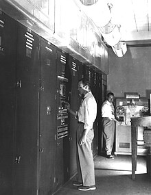
EDVAC, one of the first electronic stored program computers.

Computers such as the ENIAC had to be physically rewired in order to perform different tasks, which caused these machines to be called "fixed-program computers." Since the term "CPU" is generally defined as a software (computer program) execution device, the earliest devices that could rightly be called CPUs came with the advent of the stored-program computer.
The idea of a stored-program computer was already present in the design of J. Presper Eckert and John William Mauchly's ENIAC, but was initially omitted so the machine could be finished sooner. On June 30, 1945, before ENIAC was even completed, mathematician John von Neumann distributed the paper entitled First Draft of a Report on the EDVAC. It outlined the design of a stored-program computer that would eventually be completed in August 1949. EDVAC was designed to perform a certain number of instructions (or operations) of various types. These instructions could be combined to create useful programs for the EDVAC to run. Significantly, the programs written for EDVAC were stored in high-speed computer memory rather than specified by the physical wiring of the computer. This overcame a severe limitation of ENIAC, which was the considerable time and effort required to reconfigure the computer to perform a new task. With von Neumann's design, the program, or software, that EDVAC ran could be changed simply by changing the contents of the computer's memory.
While von Neumann is most often credited with the design of the stored-program computer because of his design of EDVAC, others before him, such as Konrad Zuse, had suggested and implemented similar ideas. The so-called Harvard architecture of the Harvard Mark I, which was completed before EDVAC, also utilized a stored-program design using punched paper tape rather than electronic memory. The key difference between the von Neumann and Harvard architectures is that the latter separates the storage and treatment of CPU instructions and data, while the former uses the same memory space for both. Most modern CPUs are primarily von Neumann in design, but elements of the Harvard architecture are commonly seen as well.
As a digital device, a CPU is limited to a set of discrete states, and requires some kind of switching elements to differentiate between and change states. Prior to commercial development of the transistor, electrical relays and vacuum tubes (thermionic valves) were commonly used as switching elements. Although these had distinct speed advantages over earlier, purely mechanical designs, they were unreliable for various reasons. For example, building direct current sequential logic circuits out of relays requires additional hardware to cope with the problem of contact bounce. While vacuum tubes do not suffer from contact bounce, they must heat up before becoming fully operational, and they eventually cease to function due to slow contamination of their cathodes that occurs in the course of normal operation. If a tube's vacuum seal leaks, as sometimes happens, cathode contamination is accelerated. Usually, when a tube failed, the CPU would have to be diagnosed to locate the failed component so it could be replaced. Therefore, early electronic (vacuum tube based) computers were generally faster but less reliable than electromechanical (relay based) computers.
Tube computers like EDVAC tended to average eight hours between failures, whereas relay computers like the (slower, but earlier) Harvard Mark I failed very rarely. In the end, tube based CPUs became dominant because the significant speed advantages afforded generally outweighed the reliability problems. Most of these early synchronous CPUs ran at low clock rates compared to modern microelectronic designs (see below for a discussion of clock rate). Clock signal frequencies ranging from 100 kHz to 4 MHz were very common at this time, limited largely by the speed of the switching devices they were built with.

Operation
The fundamental operation of most CPUs, regardless of the physical form they take, is to execute a sequence of stored instructions called a program. The program is represented by a series of numbers that are kept in some kind of computer memory. There are four steps that nearly all CPUs use in their operation: fetch, decode, execute, and writeback.
The first step, fetch, involves retrieving an instruction (which is represented by a number or sequence of numbers) from program memory. The location in program memory is determined by a program counter (PC), which stores a number that identifies the current position in the program. In other words, the program counter keeps track of the CPU's place in the program. After an instruction is fetched, the PC is incremented by the length of the instruction word in terms of memory units. Often the instruction to be fetched must be retrieved from relatively slow memory, causing the CPU to stall while waiting for the instruction to be returned. This issue is largely addressed in modern processors by caches and pipeline architectures (see below).
The instruction that the CPU fetches from memory is used to determine what the CPU is to do. In the decode step, the instruction is broken up into parts that have significance to other portions of the CPU. The way in which the numerical instruction value is interpreted is defined by the CPU's instruction set architecture (ISA). Often, one group of numbers in the instruction, called the opcode, indicates which operation to perform. The remaining parts of the number usually provide information required for that instruction, such as operands for an addition operation. Such operands may be given as a constant value (called an immediate value), or as a place to locate a value: a register or a memory address, as determined by some addressing mode. In older designs the portions of the CPU responsible for instruction decoding were unchangeable hardware devices. However, in more abstract and complicated CPUs and ISAs, a microprogram is often used to assist in translating instructions into various configuration signals for the CPU. This microprogram is sometimes rewritable so that it can be modified to change the way the CPU decodes instructions even after it has been manufactured.
After the fetch and decode steps, the execute step is performed. During this step, various portions of the CPU are connected so they can perform the desired operation. If, for instance, an addition operation was requested, an arithmetic logic unit (ALU) will be connected to a set of inputs and a set of outputs. The inputs provide the numbers to be added, and the outputs will contain the final sum. The ALU contains the circuitry to perform simple arithmetic and logical operations on the inputs (like addition and bitwise operations). If the addition operation produces a result too large for the CPU to handle, an arithmetic overflow flag in a flags register may also be set.
The final step, writeback, simply "writes back" the results of the execute step to some form of memory. Very often the results are written to some internal CPU register for quick access by subsequent instructions. In other cases results may be written to slower, but cheaper and larger, main memory. Some types of instructions manipulate the program counter rather than directly produce result data. These are generally called "jumps" and facilitate behavior like loops, conditional program execution (through the use of a conditional jump), and functions in programs. Many instructions will also change the state of digits in a "flags" register. These flags can be used to influence how a program behaves, since they often indicate the outcome of various operations. For example, one type of "compare" instruction considers two values and sets a number in the flags register according to which one is greater. This flag could then be used by a later jump instruction to determine program flow.
After the execution of the instruction and writeback of the resulting data, the entire process repeats, with the next instruction cycle normally fetching the next-in-sequence instruction because of the incremented value in the program counter. If the completed instruction was a jump, the program counter will be modified to contain the address of the instruction that was jumped to, and program execution continues normally. In more complex CPUs than the one described here, multiple instructions can be fetched, decoded, and executed simultaneously. This section describes what is generally referred to as the "Classic RISC pipeline", which in fact is quite common among the simple CPUs used in many electronic devices (often called microcontroller). It largely ignores the important role of CPU cache, and therefore the access stage of the pipeline.

Wednesday, October 7, 2009

Video Graphics Array

Video Graphics Array (VGA) refers specifically to the display hardware first introduced with the IBM PS/2 line of computers in 1987, but through its widespread adoption has also come to mean either an analog computer display standard, the 15-pin D-subminiature VGA connector or the 640×480 resolution itself. While this resolution was superseded in the personal computer market in the 1990s, it is becoming a popular resolution on mobile devices.
VGA was the last graphical standard introduced by IBM that the majority of PC clone manufacturers conformed to, making it today (as of 2010) the lowest common denominator that all PC graphics hardware can be expected to implement without device-specific driver software. For example, the Microsoft Windows splash screen appears while the machine is still operating in VGA mode, which is the reason that this screen always appears in reduced resolution and color depth.
VGA was officially superseded by IBM's Extended Graphics Array (XGA) standard, but in reality it was superseded by numerous slightly different extensions to VGA made by clone manufacturers that came to be known collectively as Super VGA.

Hardware
VGA compared to other standard resolutions.

VGA is referred to as an "array" instead of an "adapter" because it was implemented from the start as a single chip (an ASIC), replacing the Motorola 6845 and dozens of discrete logic chips that covered the full-length ISA boards of the MDA, CGA, and EGA. Its single-chip implementation also allowed the VGA to be placed directly on a PC's motherboard with a minimum of difficulty (it only required video memory, timing crystals and an external RAMDAC), and the first IBM PS/2 models were equipped with VGA on the motherboard. (Contrast this with all of the "family one" IBM PC desktop models—the PC [machine-type 5150], PC/XT [5160], and PC AT [5170]—which required a display adapter installed in a slot in order to connect a monitor.)
The VGA specifications are as follows:

  • 256 KB Video RAM (The very first cards could be ordered with 64 KB or 128 KB of RAM at the cost of losing some video modes).
  • 16-color and 256-color modes
  • 262,144-value color palette (six bits each for red, green, and blue)
  • Selectable 25.175 MHz or 28.322 MHz master clock
  • Maximum of 800 horizontal pixels
  • Maximum of 600 lines
  • Refresh rates at up to 70 Hz
  • Vertical blank interrupt (Not all clone cards support this.)
  • Planar mode: up to 16 colors (4 bit planes)
  • Packed-pixel mode: 256 colors (Mode 13h)
  • Hardware smooth scrolling support
  • Some "Raster Ops" support
  • Barrel shifter
  • Split screen support
  • 0.7 V peak-to-peak
  • 75 ohm double-terminated impedance (18.7 mA – 13 mW)

The VGA supports both All Points Addressable graphics modes, and alphanumeric text modes. Standard graphics modes are:

  • 640×480 in 16 colors
  • 640×350 in 16 colors
  • 320×200 in 16 colors
  • 320×200 in 256 colors (Mode 13h)

As well as the standard modes, VGA can be configured to emulate many of the modes of its predecessors (EGA, CGA, and MDA). Compatibility is almost full at BIOS level, but even at register level, a very high value of compatibility is reached. VGA is not compatible with the special IBM PCjr or HGC video modes.

Tuesday, October 6, 2009

CD-ROM

CD-ROM (pronounced /ˌsiːˌdiːˈrɒm/, an acronym of "compact disc read-only memory") is a pre-pressed compact disc that contains data accessible to, but not writable by, a computer for data storage and music playback. The 1985 “Yellow Book” standard developed by Sony and Philips adapted the format to hold any form of binary data.

CD-ROMs are popularly used to distribute computer software, including games and multimedia applications, though any data can be stored (up to the capacity limit of a disc). Some CDs hold both computer data and audio with the latter capable of being played on a CD player, while data (such as software or digital video) is only usable on a computer (such as ISO 9660 format PC CD-ROMs). These are called enhanced CDs.
Although many people use lowercase letters in this acronym, proper presentation is in all capital letters with a hyphen between CD and ROM. At the time of the technology's introduction it had more capacity than computer hard drives common at the time. The reverse is now true, with hard drives far exceeding CDs, DVDs and Blu-ray, though some experimental descendants of it such as HVDs may have more space and faster data rates than today's biggest hard drive.

Media
CD-ROM discs are identical in appearance to audio CDs, and data are stored and retrieved in a very similar manner (only differing from audio CDs in the standards used to store the data). Discs are made from a 1.2 mm thick disc of polycarbonate plastic, with a thin layer of aluminium to make a reflective surface. The most common size of CD-ROM disc is 120 mm in diameter, though the smaller Mini CD standard with an 80 mm diameter, as well as numerous non-standard sizes and shapes (e.g., business card-sized media) are also available. Data is stored on the disc as a series of microscopic indentations. A laser is shone onto the reflective surface of the disc to read the pattern of pits and lands ("pits", with the gaps between them referred to as "lands"). Because the depth of the pits is approximately one-quarter to one-sixth of the wavelength of the laser light used to read the disc, the reflected beam's phase is shifted in relation to the incoming beam, causing destructive interference and reducing the reflected beam's intensity. This pattern of changing intensity of the reflected beam is converted into binary data.

Standard
Several formats are used for data stored on compact discs, known as the Rainbow Books. These include the original Red Book standards for CD audio, White Book and Yellow Book CD-ROM. The ISO/IEC 10149 / ECMA-130 standard, which gives a thorough description of the physics and physical layer of the CD-ROM, inclusive of cross-interleaved Reed-Solomon coding (CIRC) and eight-to-fourteen modulation (EFM), can be downloaded from ISO or ECMA.
ISO 9660 defines the standard file system of a CD-ROM, although it is due to be replaced by ISO 13490 (which also supports CD-R and multi-session). UDF extends ISO 13346 (which was designed for non-sequential write-once and re-writeable discs such as CD-R and CD-RW) to support read-only and re-writeable media and was first adopted for DVD. The bootable CD specification, to make a CD emulate a hard disk or floppy, is called El Torito.
CD-ROM drives are rated with a speed factor relative to music CDs (1× or 1-speed which gives a data transfer rate of 150 KiB/s). 12× drives were common beginning in early 1997. Above 12× speed, there are problems with vibration and heat. Constant angular velocity (CAV) drives give speeds up to 30× at the outer edge of the disc with the same rotational speed as a standard constant linear velocity (CLV) 12×, or 32× with a slight increase. However due to the nature of CAV (linear speed at the inner edge is still only 12×, increasing smoothly in-between) the actual throughput increase is less than 30/12 – in fact, roughly 20× average for a completely full disc, and even less for a partially filled one.
Problems with vibration, owing to e.g. limits on achievable symmetry and strength in mass produced media, mean that CDROM drive speeds have not massively increased since the late 90s. Over 10 years later, commonly available drives vary between 24× (slimline and portable units, 10× spin speed) and 52× (typically CD- and read-only units, 21× spin speed), all using CAV to achieve their claimed "max" speeds, with 32× through 48× most common. Even so, these speeds can cause poor reading (drive error correction having become very sophisticated in response) and even shattering of poorly made or physically damaged media, with small cracks rapidly growing into catastrophic breakages when centripetally stressed at 10,000 – 13,000rpm (i.e. 40–52× CAV). High rotational speeds also produce undesirable noise from disc vibration, rushing air and the spindle motor itself. Thankfully, most 21st century drives allow forced low speed modes (by use of small utility programs) for the sake of safety, accurate reading or silence, and will automatically fall back if a large number of sequential read errors and retries are encountered.
Other methods of improving read speed were trialled such as using multiple pickup heads, increasing throughput up to 72× with a 10× spin speed, but along with other technologies like 90~99 minute recordable media and "double density" recorders, their utility was nullified by the introduction of consumer DVDROM drives capable of consistent 36× CDROM speeds (4× DVD) or higher. Additionally, with a 700mb CDROM fully readable in under 2½ minutes at 52× CAV, increases in actual data transfer rate are decreasingly influential on overall effective drive speed when taken into consideration with other factors such as loading/unloading, media recognition, spin up/down and random seek times, making for much decreased returns on development investment. A similar stratification effect has since been seen in DVD development where maximum speed has stabilised at 16× CAV (with exceptional cases between 18× and 22×) and capacity at 4.3 and 8.5GiB (single and dual layer), with higher speed and capacity needs instead being catered to by Blu-Ray drives.

CD-ROM format
A CD-ROM sector contains 2,352 bytes, divided into 98 24-byte frames. Unlike a music CD, a CD-ROM cannot rely on error concealment by interpolation, and therefore requires a higher reliability of the retrieved data. In order to achieve improved error correction and detection, a CD-ROM has a third layer of Reed–Solomon error correction. A Mode-1 CD-ROM, which has the full three layers of error correction data, contains a net 2,048 bytes of the available 2,352 per sector. In a Mode-2 CD-ROM, which is mostly used for video files, there are 2,336 user-available bytes per sector. The net byte rate of a Mode-1 CD-ROM, based on comparison to CDDA audio standards, is 44100 Hz × 16 bits/sample × 2 channels × 2,048 / 2,352 /8 = 153.6 kB/s = 150 KiB/s. The playing time is 74 minutes, or 4,440 seconds, so that the net capacity of a Mode-1 CD-ROM is 682 MB or, equivalently, 650 MiB.
A 1× speed CD drive reads 75 consecutive sectors per second.

Wednesday, September 23, 2009

Hard Disk Drive

A hard disk drive (HDD) is a non-volatile, random access device for digital data. It features rotating rigid platters on a motor-driven spindle within a protective enclosure. Data is magnetically read and written on the platter by read/write heads that float on a film of air above the platters.

Introduced by IBM in 1956, hard disk drives have fallen in cost and physical size over the years while dramatically increasing capacity. Hard disk drives have been the dominant device for secondary storage of data in general purpose computers since the early 1960s. They have maintained this position because advances in their areal recording density have kept pace with the requirements for secondary storage. Today's HDDs operate on high-speed serial interfaces; i.e., serial ATA (SATA) or serial attached SCSI (SAS).

History
Hard disk drives were introduced in 1956 as data storage for an IBM accounting computer) and were developed for use with general purpose mainframe and mini computers.
Driven by areal density doubling every two to four years since their invention, HDDs have changed in many ways, a few highlights include:
Capacity per HDD increasing from 3.75 megabytes to greater than 1 terabyte, a greater than 270 thousand to 1 improvement.
Size of HDD decreasing from 87.9 cubic feet (a double wide refrigerator) to 0.002 cubic feet (2½-inch form factor, a pack of cards), a greater than 44 thousand to 1 improvement.
Price decreasing from about $15,000 per megabyte to less than $0.0001 per megabyte ($100/1 terabyte), a greater than 150 million to 1 improvement
Average access time decreasing from greater than 0.1 second to a few thousandths of a second, a greater than 40 to 1 improvement.
Market application expanding from general purpose computers to most computing applications including consumer applications.

Technology

Magnetic recording
HDDs record data by magnetizing ferromagnetic material directionally. Sequential changes in the direction of magnetization represent patterns of binary data bits. The data are read from the disk by detecting the transitions in magnetization and decoding the originally written data. Different encoding schemes, such as Modified Frequency Modulation, group code recording, run-length limited encoding, and others are used.
A typical HDD design consists of a spindle that holds flat circular disks called platters, onto which the data are recorded. The platters are made from a non-magnetic material, usually aluminum alloy or glass, and are coated with a shallow layer of magnetic material, typically 10–20 nm in depth—for reference, standard copy paper is 0.07–0.18 millimetre (70,000–180,000 nm)—with an outer layer of carbon for protection.
The platters are spun at speeds varying from 3,000 RPM in energy-efficient portable devices, to 15,000 RPM for high performance servers. Information is written to, and read from a platter as it rotates past devices called read-and-write heads that operate very close (tens of nanometers in new drives) over the magnetic surface. The read-and-write head is used to detect and modify the magnetization of the material immediately under it. In modern drives there is one head for each magnetic platter surface on the spindle, mounted on a common arm. An actuator arm (or access arm) moves the heads on an arc (roughly radially) across the platters as they spin, allowing each head to access almost the entire surface of the platter as it spins. The arm is moved using a voice coil actuator or in some older designs a stepper motor.
The magnetic surface of each platter is conceptually divided into many small sub-micrometer-sized magnetic regions referred to as magnetic domains. In older disk designs the regions were oriented horizontally and parallel to the disk surface, but beginning about 2005, the orientation was changed to perpendicular to allow for closer magnetic domain spacing. Due to the polycrystalline nature of the magnetic material each of these magnetic regions is composed of a few hundred magnetic grains. Magnetic grains are typically 10 nm in size and each form a single magnetic domain. Each magnetic region in total forms a magnetic dipole which generates a magnetic field.
For reliable storage of data, the recording material needs to resist self-demagnetization, which occurs when the magnetic domains repel each other. Magnetic domains written too densely together to a weakly magnetizable material will degrade over time due to physical rotation of one or more domains to cancel out these forces. The domains rotate sideways to a halfway position that weakens the readability of the domain and relieves the magnetic stresses. Older hard disks used iron(III) oxide as the magnetic material, but current disks use a cobalt-based alloy.
A write head magnetizes a region by generating a strong local magnetic field. Early HDDs used an electromagnet both to magnetize the region and to then read its magnetic field by using electromagnetic induction. Later versions of inductive heads included metal in Gap (MIG) heads and thin film heads. As data density increased, read heads using magnetoresistance (MR) came into use; the electrical resistance of the head changed according to the strength of the magnetism from the platter. Later development made use of spintronics; in these heads, the magnetoresistive effect was much greater than in earlier types, and was dubbed "giant" magnetoresistance (GMR). In today's heads, the read and write elements are separate, but in close proximity, on the head portion of an actuator arm. The read element is typically magneto-resistive while the write element is typically thin-film inductive.
The heads are kept from contacting the platter surface by the air that is extremely close to the platter; that air moves at or near the platter speed. The record and playback head are mounted on a block called a slider, and the surface next to the platter is shaped to keep it just barely out of contact. This forms a type of air bearing.
In modern drives, the small size of the magnetic regions creates the danger that their magnetic state might be lost because of thermal effects. To counter this, the platters are coated with two parallel magnetic layers, separated by a 3-atom layer of the non-magnetic element ruthenium, and the two layers are magnetized in opposite orientation, thus reinforcing each other. Another technology used to overcome thermal effects to allow greater recording densities is perpendicular recording, first shipped in 2005, and as of 2007 the technology was used in many HDDs.

Components
A typical hard drive has two electric motors, one to spin the disks and one to position the read/write head assembly. The disk motor has an external rotor attached to the platters; the stator windings are fixed in place. The actuator has a read-write head under the tip of its very end (near center); a thin printed-circuit cable connects the read-write head to the hub of the actuator. A flexible, somewhat U-shaped, ribbon cable, seen edge-on below and to the left of the actuator arm in the first image and more clearly in the second, continues the connection from the head to the controller board on the opposite side.
The head support arm is very light, but also stiff; in modern drives, acceleration at the head reaches 550 Gs.
The silver-colored structure at the upper left of the first image is the top plate of the permanent-magnet and moving coil motor that swings the heads to the desired position (it is shown removed in the second image). The plate supports a squat neodymium-iron-boron (NIB) high-flux magnet. Beneath this plate is the moving coil, often referred to as the voice coil by analogy to the coil in loudspeakers, which is attached to the actuator hub, and beneath that is a second NIB magnet, mounted on the bottom plate of the motor (some drives only have one magnet).
The voice coil itself is shaped rather like an arrowhead, and made of doubly coated copper magnet wire. The inner layer is insulation, and the outer is thermoplastic, which bonds the coil together after it is wound on a form, making it self-supporting. The portions of the coil along the two sides of the arrowhead (which point to the actuator bearing center) interact with the magnetic field, developing a tangential force that rotates the actuator. Current flowing radially outward along one side of the arrowhead and radially inward on the other produces the tangential force. If the magnetic field were uniform, each side would generate opposing forces that would cancel each other out. Therefore the surface of the magnet is half N pole, half S pole, with the radial dividing line in the middle, causing the two sides of the coil to see opposite magnetic fields and produce forces that add instead of canceling. Currents along the top and bottom of the coil produce radial forces that do not rotate the head.