The current Parallel ATA standard is the result of a long history of incremental technical development, which began with the original AT Attachment interface, developed for use in early PC AT equipment. The ATA interface itself evolved in several stages from Western Digital's original Integrated Drive Electronics (IDE) interface. As a result, many near-synonyms for ATA/ATAPI and its previous incarnations exist, including abbreviations such as IDE which are still in common informal use. After the market introduction of Serial ATA in 2003, the original ATA was retroactively renamed Parallel ATA.
Parallel ATA only allows cable lengths up to 18 in (457 mm). Because of this length limit the technology normally appears as an internal computer storage interface. For many years ATA provided the most common and the least expensive interface for this application. By the beginning of 2007, it had largely been replaced by Serial ATA (SATA) in new systems.
History and terminology
The standard was originally conceived as "PC/AT Attachment" as its primary feature was a direct connection to the 16-bit ISA bus introduced with the IBM PC/AT. The name was shortened to "AT Attachment" to avoid possible trademark issues. It is not spelled out as "Advanced Technology" anywhere in current or recent versions of the specification; it is simply "AT Attachment".
Parallel ATA interface
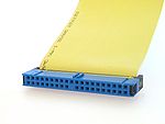
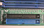
Until the introduction of Serial ATA, 40-pin connectors generally attached drives to a ribbon cable. Each cable has two or three connectors, one of which plugs into an adapter interfacing with the rest of the computer system. The remaining connector(s) plug into drives. Parallel ATA cables transfer data 16 bits at a time.
ATA's ribbon cables have had 40 wires for most of its history (44 conductors for the smaller form-factor version used for 2.5" drives — the extra four for power), but an 80-wire version appeared with the introduction of the Ultra DMA/33 (UDMA) mode. All of the additional wires in the new cable are ground wires, interleaved with the previously defined wires to reduce the effects of capacitive coupling between neighboring signal wires, reducing crosstalk. Capacitive coupling is more of a problem at higher transfer rates, and this change was necessary to enable the 66 megabytes per second (MB/s) transfer rate of UDMA4 to work reliably. The faster UDMA5 and UDMA6 modes also require 80-conductor cables.
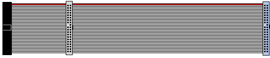
Though the number of wires doubled, the number of connector pins and the pinout remain the same as 40-conductor cables, and the external appearance of the connectors is identical. Internally the connectors are different; the connectors for the 80-wire cable connect a larger number of ground wires to a smaller number of ground pins, while the connectors for the 40-wire cable connect ground wires to ground pins one-for-one. 80-wire cables usually come with three differently colored connectors (blue — controller, gray — slave drive, and black — master drive) as opposed to uniformly colored 40-wire cable's connectors (all black). The gray connector on 80-conductor cables has pin 28 CSEL not connected; making it the slave position for drives configured cable select.
Pin 20
In the ATA standard pin 20 is defined as (mechanical) key and is not used; i.e., this socket on the female connector is often obstructed, and a cable or drive connector with a pin in this position cannot be connected, making it impossible to plug in a connector the wrong way round. However, some flash memory drives can use pin 20 as VCC_in to power the drive without requiring a special power cable.
Pin 28
Pin 28 of the gray (slave/middle) connector of an 80 conductor cable is not attached to any conductor of the cable. It is attached normally on the black (master drive end) and blue (motherboard end) connectors.
Pin 34
Pin 34 is connected to ground inside the blue connector of an 80 conductor cable but not attached to any conductor of the cable. It is attached normally on the gray and black connectors. See page 315 of.


